Verilog for Beginners: Your First Module in 15 Minutes
Verilog is the language engineers use to describe digital circuits — from a single gate to an entire processor. If you have built circuits in a visual simulator, Verilog is the next step: you'll learn to describe the same circuits as text. And there is nothing to install: it all runs in the browser at level 30 of the Ershov Computer simulator.
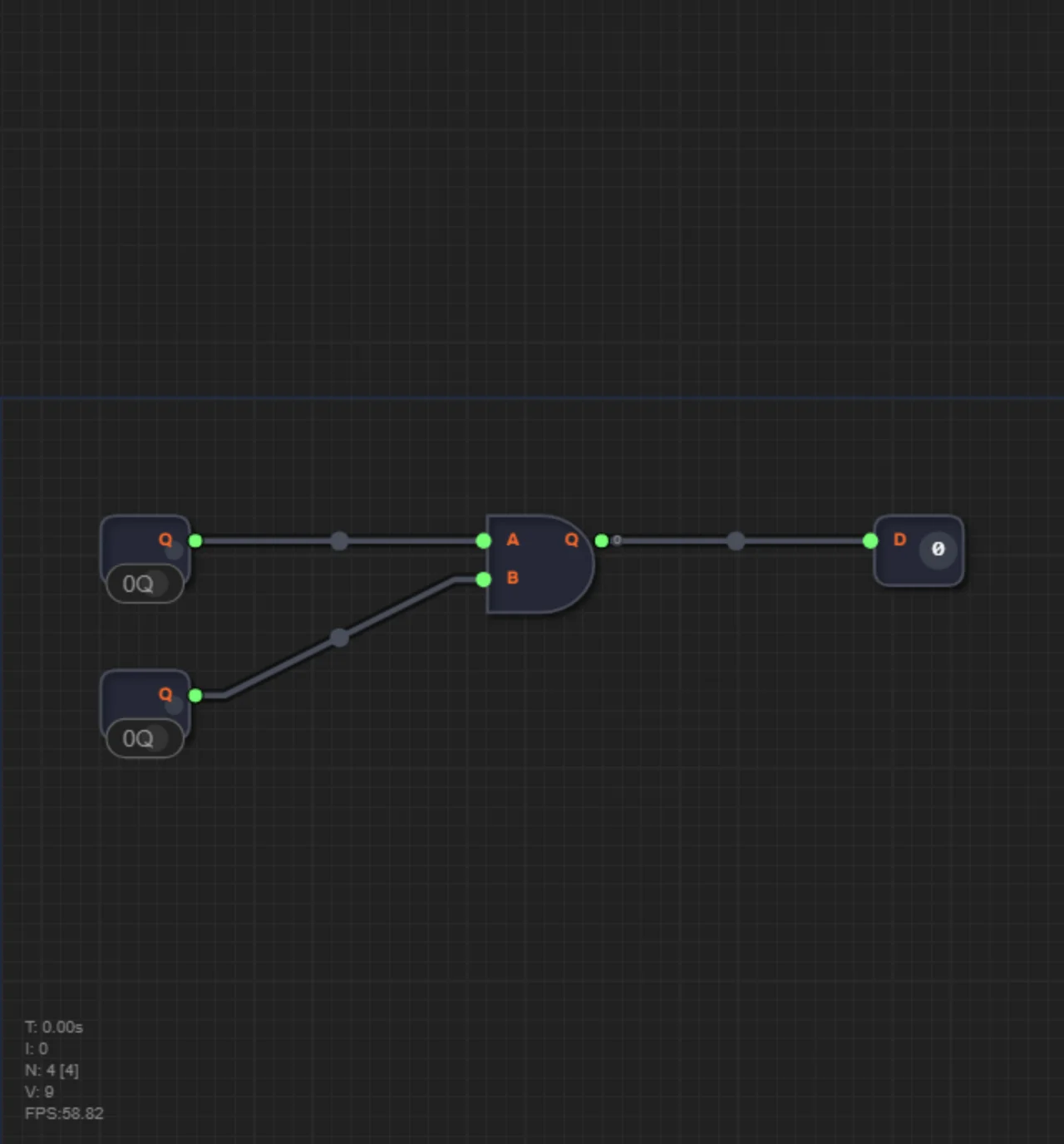
How Verilog differs from an ordinary programming language
A Python or C++ program is executed sequentially, instruction by instruction. A Verilog module describes a circuit where all elements work simultaneously. That is why Verilog has no familiar loops and no "variables" in the programming-language sense — instead, wires and logic elements.
The most important difference: a module written in Verilog can be synthesized into a real chip or flashed into an FPGA. Code becomes hardware. Why Verilog is not programming is explained in Silicon Instead of Code.
Your first module: a wire
A module is a "building block" of a circuit with inputs and outputs. The simplest module just connects an input to an output — a wire:
module wire_gate(
    input  a,
    output y
);
    assign y = a;
endmodule
Line by line: module wire_gate(...) declares a module named wire_gate; input a is an input signal; output y is an output; assign y = a means the output always equals the input; endmodule closes the module.
This is exactly the first level of the Verilog part: level 30 "Hello, Wire!". A starter module is already open in the editor on the right — figure out what to fix and press Play.
A NOT gate in 30 seconds
Inverting a signal is one line:
module not_gate(
    input  a,
    output y
);
    assign y = ~a;
endmodule
The ~ symbol is negation. If the input is 0, the output is 1, and vice versa.
A multiplexer: when there are several signals
A multiplexer picks one of its inputs according to sel. In Verilog it can be described with a ternary-like statement:
module mux2(
    input      a, b,
    input      sel,
    output reg y
);
    always @(*) begin
        if (sel) y = b;
        else     y = a;
    end
endmodule
The always @(*) block means "recompute on any input change", and if (sel) ... else ... chooses which input goes to the output. That is how level 32 "Flow Control (MUX)" works. More about multiplexers without if/else — in How Hardware Makes Decisions.
An adder: teaching silicon to add
Arithmetic in Verilog looks surprisingly simple — with the "+" symbol:
module adder8(
    input  [7:0] a, b,
    output [8:0] sum
);
    assign sum = a + b;
endmodule
The notation [7:0] says the signal is an 8-bit bus, and [8:0] is 9 bits (with carry). The line assign sum = a + b synthesizes into a real chain of adders — this is how a circuit "learns" to count. Behind it lies real mechanics — see Teaching Silicon Math.
Hierarchy: modules inside modules
Big circuits are built from small ones. An adder module can be used inside another module — that is called hierarchy:
module full_adder_8(
    input  [7:0] a, b,
    input        cin,
    output [7:0] sum,
    output       cout
);
    wire [8:0] t;
    adder8 u_adder(.a(a), .b(b), .sum(t));
    assign sum  = t[7:0];
    assign cout = t[8];
endmodule
The line adder8 u_adder(...) instantiates the adder8 module and connects its ports. Processors are built from such "nesting dolls". On hierarchy — Hierarchy: How Not to Drown in Wires.
Buses and memory
Real circuits work with bytes, not single bits. Buses [7:0] carry 8 bits at once — that's the next step after single wires: level 35 "Data Buses (Adder8)". And the built-in RAM256 and ROM modules let you add memory to a processor: level 39 "Random Access Memory". All about buses — in Data Buses: From Individual Bits to Bytes.
How to practice for free
In the Ershov Computer simulator, the Verilog part starts at level 30 and takes 14 levels (30–43). The built-in editor highlights syntax, the parser finds errors, and the simulator runs the circuit against test vectors. The RTL Viewer shows how your code becomes a circuit, and waveforms show how signals change per tick.
After level 43 the most interesting part begins: on levels 44–47 you will design your own Verilog processor, and at the final level export the project to a ZIP and flash it onto a real Tang Nano 9K FPGA board. Everything about the "from code to silicon" path is gathered in the Verilog and FPGA hub.
FAQ
Do I need programming skills for Verilog?
Helpful, but not required. The key is understanding circuit logic: gates, buses, clock signals. That is exactly what the visual part of the course (levels 1–29) provides.
What do I need to install?
Nothing. Levels 30–47 run right in the browser: editor, simulator and RTL viewer are built into the page.
Can I flash the project onto a real board?
Yes. At the final level the project exports to a ZIP that opens in the Gowin IDE for the Tang Nano 9K board — an inexpensive, accessible FPGA for learning.