Silicon Instead of Code: Why Verilog Is Not Programming
You already know how to write code. You probably know what variables, for loops, arrays, and if/else conditions are. You're used to giving the computer commands, and it obediently executes them one after another.
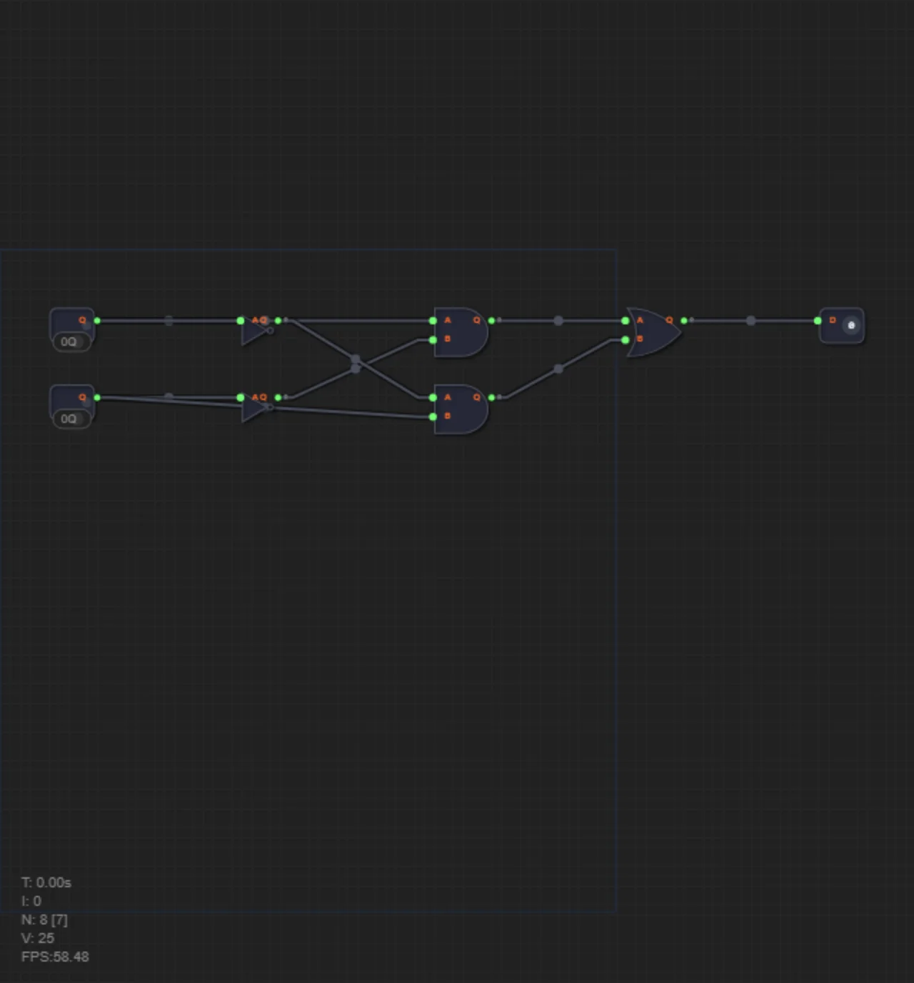
But on this level of the simulator, your programmer reflexes will play a cruel trick on you. Because Verilog is not a programming language at all.
Yes, it looks like text. It has brackets, commas, and a semicolon at the end of a line. But when you write in Verilog, you're not creating an algorithm. You are literally drawing a wiring diagram.
Welcome to the world of HDL — Hardware Description Language.
The Main Secret: There Is No Time Here
Remember how any Python or C++ code works.
x = 5       # Step 1
y = x + 2   # Step 2
print(y)    # Step 3
The computer executes line 1, then moves on to line 2, and then to line 3. This is a sequential process.
In Verilog (and in a physical processor) all lines "work" at the same time. If you wrote calls for three logic gates in your code, it doesn't mean the first one fires first and the second one after it. It means the factory will print three microchips on a piece of silicon, connect them with copper, and when power is applied they will all work in parallel.
Anatomy of a Chip: How the Code Works
Let's build a simple circuit. Say we're making a safe lock (SafeLock) that opens (open) only if a key is inserted (key) AND the alarm hasn't gone off (alarm).
In the world of hardware, any program is a chip (module). It has a plastic case and metal legs sticking out of it (pins).
module SafeLock(
    input wire key,       // Input pin (is the key inserted)
    input wire alarm,     // Input pin (is the siren wailing)
    output wire open      // Output pin (open the lock)
);
Notice the word wire. From English it translates as "wire". When you write input wire, you are literally saying: "I soldered a copper wire to the input of my chip."
Soldering the Logic
For the lock to open, we need logic: KEY AND (NOT ALARM).
We'll need two logic gates: not (inverter) and and (logical AND).
In classical programming we would write open = key and not alarm. But in structural Verilog we work with our hands — we call up specific parts from the warehouse and connect their pins.
But how do we pass the signal from the inverter to the AND gate? We'll need an internal wire.
module SafeLock(
    input wire key,
    input wire alarm,
    output wire open
);

    // 1. Cut a piece of internal wire.
    // It doesn't stick out of the chip, it's hidden inside.
    wire safe_alarm;

    // 2. Place an inverter.
    // Call syntax: part_name board_name(output, input);
    not inv1(safe_alarm, alarm);

    // 3. Place an AND gate.
    // Connect the key and our internal wire to it. Send the result outside.
    and and1(open, key, safe_alarm);

endmodule
Debriefing
Look at the code above. What fires first: not or and?
Answer: nothing. This is just a blueprint.
When you press the "Synthesize" button, the simulator reads this text and draws the circuit: it takes the alarm input, runs it through the not gate, runs the result along the copper wire safe_alarm to the input of the and gate, and connects the key wire to its second input.
Verilog's Golden Rule: When writing code, imagine you have a soldering iron in one hand and a coil of wire in the other. You are not ordering the processor what to do. You are creating the processor.
In level 30 you will apply this approach for the first time. You'll need to build an Exclusive OR gate (XOR) using only basic elements. Get your soldering iron ready — we're moving to silicon.