How Hardware Makes Decisions (Life Without if/else)
In programming, nothing is more natural than branching. You write if (condition) { do_a(); } else { do_b(); } and don't think about how it works. The computer simply checks the condition and goes strictly down one branch of the code. The other branch sleeps at that moment — it isn't even launched, saving the processor's resources.
In hardware development in structural Verilog the if statement does not exist.
Electric current doesn't read code and can't think. It flows along all physically available copper traces simultaneously. If a chip has two possible ways for events to develop (for example, adding numbers or subtracting them), silicon will do both at once.
So how does the processor choose the right answer and discard the unnecessary one?
Meet the Multiplexer (Mux)
To route the current in the right direction, engineers invented multiplexers. A multiplexer (or simply Mux) is a hardware "switchman". It's a physical switch that has several data inputs, one output, and a special control pin.
Let's look at the simplest 2-to-1 Multiplexer. It has:
- Two data inputs:
aandb. - One control input:
sel(from the word select). - One output:
out.
The logic of operation is iron (literally):
- If a 0 (no voltage) is applied to the
selpin, the switch connects the output to theawire. - If a 1 (voltage present) is applied to the
selpin, the switch "throws the rails" and passes thebsignal to the output.
Anatomy of the Switch: Building a Mux from Basic Gates
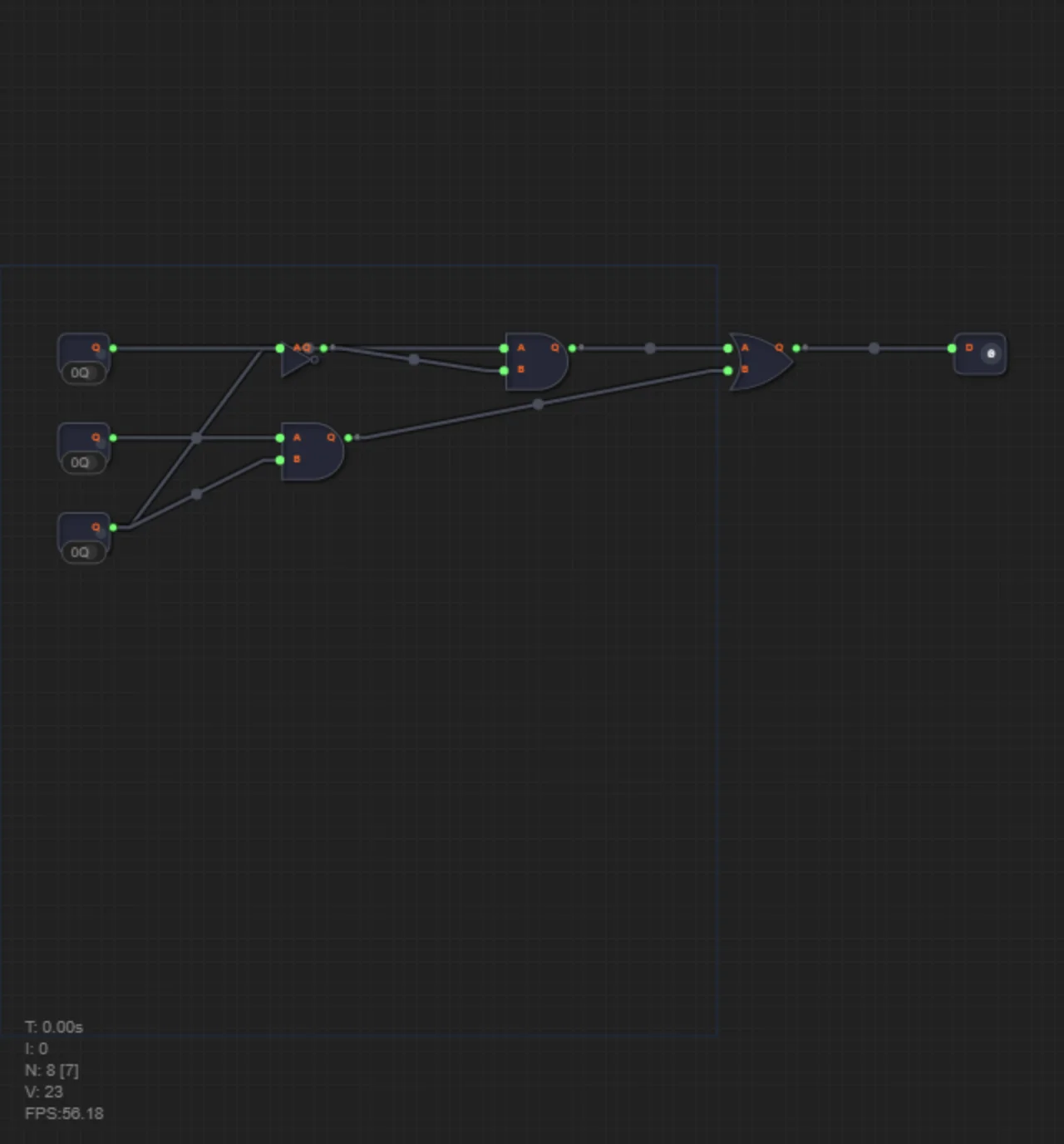
How do you make dumb logic gates work like a smart switch? We'll need two "guards" (and gates) and one "collector" (or gate).
Let's recall how the and gate (logical AND) works. It outputs a one only if both of its inputs receive ones. If a strict 0 hangs on at least one input, the and gate is blocked — it will output 0 no matter what happens on the second wire. It's the perfect barrier gate!
Here's how the multiplexer circuit is built:
- Create an inverted switch. We need the first guard to open when
sel = 0. To do this, we run theselwire through anotgate. - Place the first guard for signal A. Take an
andgate. Feed our dataato one of its inputs, and the invertedselto the second. Now signalacan pass through this gate only whenselwas originally zero. - Place the second guard for signal B. Take the second
andgate. Feed it databand the direct (non-inverted)selwire. Signalbwill pass further only whenselequals one. - Combine everything. Since
selcan't be both zero and one at the same time, only one of the guards will pass its signal. To bring the winning signal outside, we simply direct the outputs of bothandgates into the finalorgate (logical OR).
The engineers' secret: In programming we write
if/elseto save computations. In circuit design we compute absolutely everything in parallel, spending transistors on it, and then simply place a Mux so it "silences" the unnecessary results and lets only one correct answer through. This is the foundation of the incredible speed of modern processors.
In level 3.1 you will transfer this logic into textual code for the first time. Remember everything you learned about internal wires (wire) — you'll need to create them for the outputs of the guard gates in order to connect them to the collector. Good luck!