Data Buses: From Individual Bits to Bytes
In the previous article we built a FullAdder — a module that adds three bits (a, b, and a carry) and outputs one sum bit and one carry bit.
But let's imagine: we have two 8-bit numbers to add. Say, 113 (01110001) and 29 (00011101). How do we do it if we only have a single-bit FullAdder?
The obvious solution comes to mind: take 8 Full Adders, connect them in series, feed each one the corresponding bits of the numbers, and feed the carry from the previous one into the next one's input. And that is the right solution.
But how do we write this in Verilog? Surely we don't have to declare 16 separate inputs (a0, a1, ..., a7, b0, b1, ..., b7) and 16 intermediate wires? That's 32 names, 32 lines of declarations, and every wire has to be connected by hand. For 8-bit addition that's already tedious, and for 64-bit — practically impossible.
Fortunately, Verilog has the concept of a bus, or a vector.
What Is a Bus and Why Do You Need It
In a real digital device, data almost never travels over a single wire. When a processor reads an 8-bit value from memory, it needs 8 wires, one per bit. These 8 wires, laid out in parallel, form a data bus.
In Verilog, a bus is declared with a range in square brackets:
input  [7:0] a;   // 8-bit input a (bits 7 down to 0)
input  [7:0] b;   // 8-bit input b
output [7:0] sum; // 8-bit output sum
output       cout; // 1-bit carry output
The notation [7:0] reads as "from 7 to 0 inclusive". The first number (7) is the most significant bit (MSB, Most Significant Bit). The last (0) is the least significant bit (LSB).
How to Access Individual Bus Bits
A vector is essentially an array of wires. You can access any bit by index:
wire [7:0] data;
wire lsb = data[0];  // least significant bit (bit 0)
wire msb = data[7];  // most significant bit (bit 7)
You can select a range of bits (part-select):
wire [3:0] low_nibble  = data[3:0];  // the low 4 bits
wire [3:0] high_nibble = data[7:4];  // the high 4 bits
Building the Ripple Carry Adder
Now we have the tool to build an 8-bit adder. The idea is simple: take 8 FullAdder instances, connect them in a chain, where the carry from each previous one feeds into the next one's input. This design is called a Ripple Carry Adder — "an adder with a rippling carry".
Why "rippling"? Because the carry runs along the chain of adders like a "wave" (ripple): first the least significant bit computes, emits a carry, it runs to the next one, the next one computes with the carry in mind, emits its own carry, and so on all the way to the most significant bit.
Notice: the least significant adder (FA 0) has its cin input connected to 0, because there's nowhere to carry from "bit -1". The most significant one's cout output is the global carry, which signals overflow (the result didn't fit into 8 bits).
Writing the Code: 8x FullAdder by Hand
module RippleCarryAdder8(
    input  [7:0] a,
    input  [7:0] b,
    output [7:0] sum,
    output       cout
);
    wire [7:0] c;

    FullAdder fa0 (.a(a[0]), .b(b[0]), .cin(1'b0), .sum(sum[0]), .cout(c[0]));
    FullAdder fa1 (.a(a[1]), .b(b[1]), .cin(c[0]), .sum(sum[1]), .cout(c[1]));
    FullAdder fa2 (.a(a[2]), .b(b[2]), .cin(c[1]), .sum(sum[2]), .cout(c[2]));
    FullAdder fa3 (.a(a[3]), .b(b[3]), .cin(c[2]), .sum(sum[3]), .cout(c[3]));
    FullAdder fa4 (.a(a[4]), .b(b[4]), .cin(c[3]), .sum(sum[4]), .cout(c[4]));
    FullAdder fa5 (.a(a[5]), .b(b[5]), .cin(c[4]), .sum(sum[5]), .cout(c[5]));
    FullAdder fa6 (.a(a[6]), .b(b[6]), .cin(c[5]), .sum(sum[6]), .cout(c[6]));
    FullAdder fa7 (.a(a[7]), .b(b[7]), .cin(c[6]), .sum(sum[7]), .cout(cout));
endmodule
The code is a bit long, but it's crystal clear: each of the 8 bits is added separately, and the carries are passed along the chain.
Taming Repetition with generate
module RippleCarryAdder8(
    input  [7:0] a,
    input  [7:0] b,
    output [7:0] sum,
    output       cout
);
    wire [8:0] c;
    assign c[0] = 1'b0;

    genvar i;
    generate
        for (i = 0; i < 8; i = i + 1) begin : fa_chain
            FullAdder fa (
                .a(a[i]), .b(b[i]), .cin(c[i]),
                .sum(sum[i]), .cout(c[i+1])
            );
        end
    endgenerate

    assign cout = c[8];
endmodule
generate is a synthesis-time directive that lets you create repeating structures. Imagine a for loop, but not during program execution — during circuit assembly.
How the Carry "Ripples"
Every logic gate has a signal propagation delay. When a[0] and b[0] change, FA0 computes sum[0] and c[1]. For FA1 to start computing, it has to wait for c[1]. When FA1 finishes, c[2] runs to FA2... and so on, like a wave.
The delay grows linearly: for an 8-bit adder it's ~48 gate delays, for a 64-bit one — ~384. This is called the critical path. The longer the critical path, the slower the processor can run.
That's exactly why real processors don't use 64-bit Ripple Carry Adders — the delay is too great. Instead, trickier circuits are used: the Carry Lookahead Adder (an adder with accelerated carry).
Another Example: Bus Concatenation
wire [7:0] a = 8'b10101010;
wire [15:0] word = {a, b}; // 16-bit word

// Concatenation: assembling a bus from individual bits
wire [7:0] d = {a[0], a[1], a[2], a[3], a[4], a[5], a[6], a[7]};
Concatenation {...} is a powerful tool. It works like "assembling" a bus from pieces.
Summary
1. Buses (vectors) are declared with a range [7:0] and let you work with a group of wires as a single whole.
2. Individual bus bits can be accessed by index: a[3], a[0].
3. Ripple Carry Adder is a chain of FullAdders, where the carry of each previous adder feeds into the next one's input.
4. For repeating structures, generate is used — a "loop during synthesis".
5. Signal propagation delay (ripple delay) is the main problem of sequential carry.
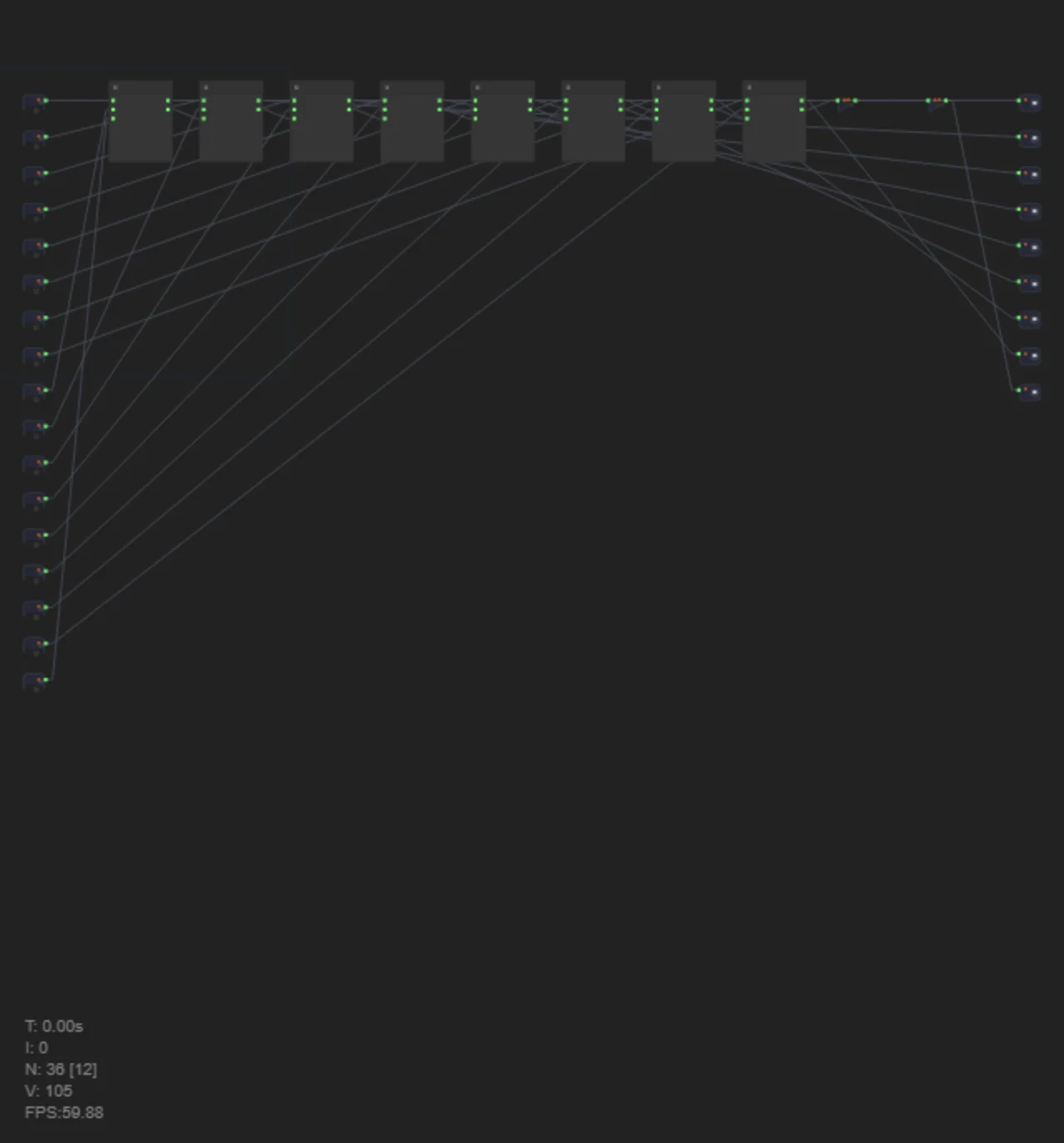
In level 3.35 you will build an 8-bit Ripple Carry Adder, using 8 FullAdder instances (which you built in level 3.34) and bus routing from two 8-bit inputs to an 8-bit output. Try both ways: manual and with generate.