Hierarchy: How Not to Drown in Wires
In the previous article you built your first real computing block — the Half Adder. Two inputs, two outputs, a couple of gates — XOR for the sum and AND for the carry. Simple, elegant, it works.
But let's face the truth: the Half Adder can only add one bit. And what if we need to add 113 and 29? 113 in binary is 01110001. Nine bits. We'll need to add them digit by digit, and each digit depends on the carry of the previous one.
And here we run into the problem: the Half Adder has only two inputs. It has no input for the carry. But real column addition (remember school!) looks like this: you add up the digits of the digit place, add to them what's "in your head" from the previous digit, write down the result, and pass the new carry further. Three input signals, not two.
We need a Full Adder.
The Third Input: Carry In
The Full Adder is an evolution of the Half Adder. Its main superpower: it has a third input cin (carry in — "the carry at the input").
The module signature:
module FullAdder(
    input  a,
    input  b,
    input  cin,
    output sum,
    output cout
);
Three inputs, two outputs. The sum output is the result of adding a + b + cin. The cout output is the new carry into the next digit (that very "one in your head").
Let's recall the binary arithmetic from the first article. Addition in binary is simple: 0+0=0, 0+1=1, 1+1=0 with a carry of 1. And now we have three addends. How many combinations are there total? 2³ = 8. And here is the full truth table:
a  b  cin │ sum  cout
──────────┼─────────
0  0  0   │  0    0
0  0  1   │  1    0
0  1  0   │  1    0
0  1  1   │  0    1
1  0  0   │  1    0
1  0  1   │  0    1
1  1  0   │  0    1
1  1  1   │  1    1
Notice the pattern: sum is 1 when the number of ones among the inputs is odd (1 or 3). And cout is 1 when the number of ones is 2 or more. Simple? Simple. But how do we implement it?
Two Half Adders + One OR
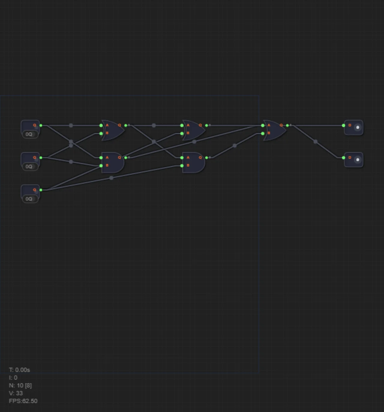
And here is the main trick of the whole article. The Full Adder can be built from two Half Adder instances and one OR gate. Let's break down this assembly step by step.
Step 1. Feed a and b into the first Half Adder. On its outputs, s1 is a XOR b, and c1 is a AND b.
Step 2. Feed s1 (the result of the first Half Adder) together with cin into the second Half Adder. On its outputs, sum is the final sum s1 XOR cin, and c2 is s1 AND cin.
Step 3. The final carry cout is c1 OR c2. Why OR and not XOR? Because a carry could arise both at the first stage (if a and b are both 1) and at the second (if s1 and cin are both 1). Since these situations cannot happen at the same time (easy to verify from the truth table), OR covers both cases.
The result is a concise, hierarchical structure: the complex is built from the simple.
Back to 1970: Why Hierarchy Matters
Imagine you're an engineer in the early 1970s designing the Intel 4004 — the world's first commercial microprocessor. It has about 2300 transistors. If every transistor were designed from scratch, the blueprints would take up a whole wall. Nobody could keep track of that many connections.
But engineers don't draw every transistor individually. They assemble them into logic gates (AND, OR, NOT), from the gates they build functional blocks (adders, multiplexers, registers), and from those blocks — the whole processor. Each level of abstraction hides the internal complexity and exposes only the interface (inputs and outputs).
In programming you call this a function or a class. You once wrote a function calculateTotal(items) — and now you call it from a hundred different places without thinking about what loops and conditions are inside.
In Verilog this is called a module and its instantiation.
Module Instantiation: How to "Call" Hardware
When you wrote module HalfAdder(...), you described how the Half Adder is built. But by itself this code doesn't create any gates in the circuit. To actually place a Half Adder inside another module, you need to instantiate it — that is, create a concrete instance.
The syntax is very similar to a function call, but don't be confused: instantiation happens at the "compilation" stage of the circuit (synthesis), not during operation.
Method 1: Named Connection (Recommended)
HalfAdder ha1 (
    .a(a),
    .b(b),
    .sum(s1),
    .cout(c1)
);
HalfAdder is the module name (type). ha1 is the name of the concrete instance. In parentheses we explicitly write: "connect signal a from the current module to port .a of the HalfAdder module".
Method 2: Positional Connection
HalfAdder ha2 (s1, cin, sum, c2);Here the order of signals must strictly match the order of ports in the module declaration.
Building a FullAdder from Two Half Adders
module FullAdder(
    input  a,
    input  b,
    input  cin,
    output sum,
    output cout
);
    wire s1;
    wire c1;
    wire c2;

    HalfAdder ha1 (
        .a(a), .b(b),
        .sum(s1), .cout(c1)
    );

    HalfAdder ha2 (
        .a(s1), .b(cin),
        .sum(sum), .cout(c2)
    );

    or (cout, c1, c2);
endmodule
See what happened? Inside the FullAdder module there isn't a single logic gate in explicit form. Instead we said: "put ha1 here, put ha2 here, add one OR". The Verilog synthesizer will expand ha1 and ha2 into their internal structure (XOR + AND), and at the physical level you'll get a circuit of three gates.
Analogy with Program Code
In software, every function call runs at its own time, on the same CPU. In hardware, every module instance is a separate piece of silicon. ha1 and ha2 exist simultaneously and work in parallel.
In software you can call a function 8 times, and it will run 8 times sequentially. In hardware you instantiate the module 8 times, and all 8 copies work simultaneously. This is the foundation of parallelism, which we'll talk about in the next article.
Tip: Give Ports Meaningful Names
Good port and signal names:
alu_result— it's clear that this is the ALU resultpc_next— the next value of the program countermem_addr— the memory address
Bad names:
sig1,tmp,out,data— unclear where from and where to
Summary
1. The Full Adder is needed to add bits taking into account the carry from the previous digit. It has three inputs (a, b, cin) and two outputs (sum, cout).
2. FullAdder is built from two Half Adders and one OR — this is the first example of hierarchical design.
3. Verilog lets you instantiate modules inside other modules, connecting ports by names (.port(signal)) or by order.
Hierarchy is not just a convenience. It's the only way to cope with the complexity of digital circuits. A processor with a billion transistors is designed as a multi-level hierarchy: transistors → gates → functional blocks → modules → cores → chip.
In level 3.3 you will build a FullAdder from two Half Adders (which you already built in level 3.2) and one OR gate. Don't forget to use named port connections — get used to good style from the very start.