Level 11: Smart memory
Open the level →Where it fits in the machine →
Task
Goal: build a D flip-flop (DFF): data is captured on the rising edge of the Clock.
A D flip-flop (DFF) captures the value on input D at the RISING EDGE of the Clock signal (the moment it transitions from 0 to 1).
The main idea: feedback invites races, so the D flip-flop is two-stage: the master listens to the data, the slave holds the output, and the write happens strictly on the clock edge. What decides when data is written is the clock, not the data.
Path to this level
The competencies this level develops and their formation levels.
Related Materials
- Clock and D Flip-Flop
- DFF (D Flip-Flop) — stores a bit
- Clock — timing generator
- How it is built from NAND — the D flip-flop circuit
Solution for self-check
Try building the circuit yourself first. The solution below is a way to check yourself if you're stuck or have already solved it.
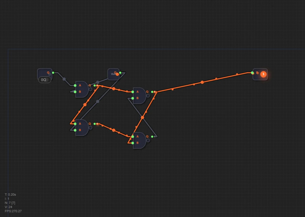
The in-game hint on this level inserts a scaffold: the circuit without two slave-stage wires — the D input and the feedback line. Connect them yourself: without them the flip-flop cannot store, which is the best demonstration of why the second NAND pair exists.
What you should get: the flip-flop stores the value on input D at the moment of the Clock edge — until the edge, changes on D do not affect the output.
The flip-flop is built in a master-slave configuration from four NAND gates:
- NAND#1: inputs A = D (data), B = Clock.
- NAND#2: inputs A = NAND#1 output, B = Clock.
- NAND#3: inputs A = NAND#1 output, B = NAND#4 output.
- NAND#4: inputs A = NAND#2 output, B = NAND#3 output.
The first pair (NAND#1+#2 — master) accepts data when Clock=1. The second pair (NAND#3+#4 — slave) stores when Clock=0.
Why two stages: while Clock=1, the master is open and passes D through, but the slave is closed — nothing is issued outside. When Clock falls to 0, the master "freezes" the value, and the slave passes it to the output. A "ragged" intermediate value never reaches Q — that is the point of the master-slave pair.
NAND#3 output (Q) is the main output. Connect Clock from the pre-placed Clock element (pre:Clock) on the canvas. This edge capture is exactly what level 16 will need: a program counter built on a transparent latch would run many steps ahead within a single tick.
Check yourself
What is the point of the two master-slave stages?
The master takes the data, the slave holds the output: an intermediate value never reaches Q, and the output changes exactly once per tick.