Level 12: Tangible Memory
Open the level →Where it fits in the machine →
Task
Goal: build an 8-bit register from DFFs and connect its output to LED8.
Build an 8-bit register from eight D flip-flops. Eight 1-bit memory cells working in parallel.
The main idea: a byte-wide register is parallelism: eight D flip-flops share one clock and hold a byte at once. Disconnect their Clock and the register freezes: memory lives exactly as long as it is clocked.
Path to this level
The competencies this level develops and their formation levels.
Related Materials
- Registers: First Byte of Memory
- Register8 — 8-bit register
- DFF — D flip-flop
Solution for self-check
Try building the circuit yourself first. The solution below is a way to check yourself if you're stuck or have already solved it.
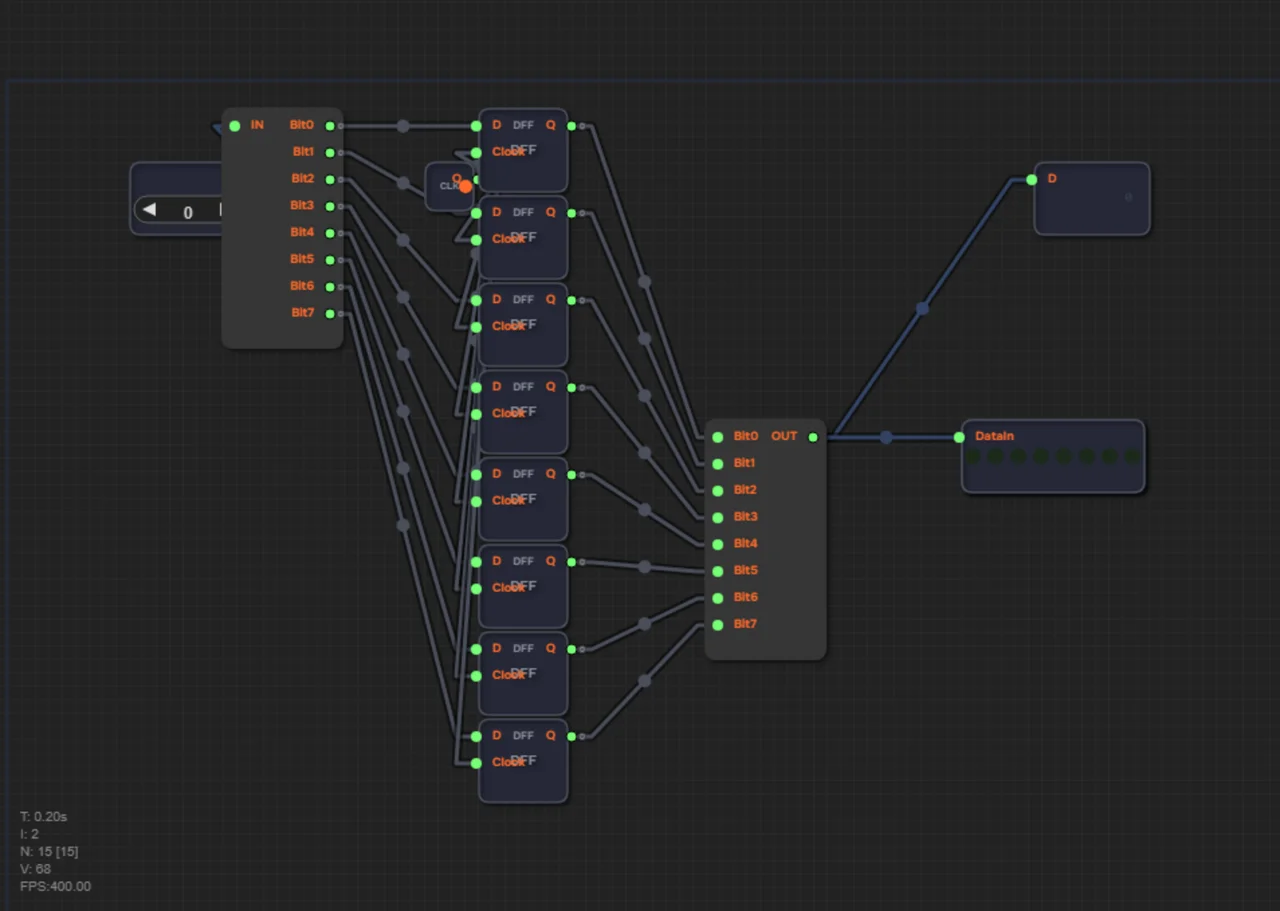
What you should get: the Data bus is split into 8 bits, each bit is stored by its own DFF on a shared Clock edge, and the assembled byte lights up on LED8.
A register is eight 1-bit memory cells working in parallel:
- Take a Splitter and feed it the Data input bus: it breaks the bus into bits Bit0…Bit7.
- Place 8 DFFs vertically one under another. Feed each D input with the corresponding bit: DFF#1 ← Bit0, DFF#2 ← Bit1, … DFF#8 ← Bit7.
- Connect Clock (already on canvas) in parallel to all DFFs — to each DFF Clock input. This way all 8 bits are written at the same time.
- Feed all DFF Q outputs to Maker: DFF#1.Q → Bit0 … DFF#8.Q → Bit7.
- Connect the Maker output (OUT) to the LED8 input (DataIn): the LEDs show the register value in binary, glowing green = 1, off = 0.
The key point is the shared tick: eight flip-flops are written by one edge, so the eight bits behave as a single byte-wide register.
Check yourself
Why is Clock connected to all eight DFFs in parallel?
A shared tick writes all 8 bits with one edge — the eight cells act as a single byte-wide register.