Clock and the D Flip-Flop
The SR latch is a great invention, but it has a problem: it's too chaotic. If signals in a large processor arrive at the inputs microseconds apart, the circuit can latch random garbage. The processor, like a large symphony orchestra, needs a conductor so all instruments play strictly in rhythm.
That conductor is the clock generator (Clock). It produces a steady pulse: tick-tock, 1-0, 1-0. The gigahertz (GHz) numbers in every PC spec are exactly this pulse rate: billions of ticks per second.
To make memory obey the conductor, engineers invented the D flip-flop. It does the same thing as the SR latch, but with one important condition: it updates its memory strictly at the "tick" of the clock — on the edge, when Clock transitions from 0 to 1. The rest of the time it's deaf to changes on the input. Thanks to this synchronous pulse, data flows through the processor in an orderly fashion, without errors.
Why a circuit needs a conductor
Remember the combinational circuits from previous levels: their output changes instantly, right after the inputs. But as soon as memory appears — SR latches, registers — time enters the game. If every latch captured data at a random moment, the result would depend on microscopic wire delays: someone made it, someone was late — and the processor would output garbage.
The solution is an agreement: let every memory cell update at only one, strictly defined moment. That moment is set by the clock generator — a single shared wire carrying a regular pulse of 1s and 0s. While the signal runs, combinational logic computes; on the edge, all flip-flops simultaneously "photograph" their inputs.
The clock generator: billions of beats per second
A processor's frequency is the number of such edges per second. A 3.5 GHz processor makes 3.5 billion clock ticks per second, and a single tick lasts just 1 / 3,500,000,000 ≈ 0.28 nanoseconds. In that time a signal must travel through dozens of gates, reach the right flip-flops, and settle — which is why engineers design critical paths so carefully.
On every tick, flip-flops across the whole chip capture new data at the same time: registers save results, the program counter updates the address, the pipeline moves an instruction one step forward. Without the clock generator, signals would collide in chaos.
The D flip-flop: memory that hears only commands
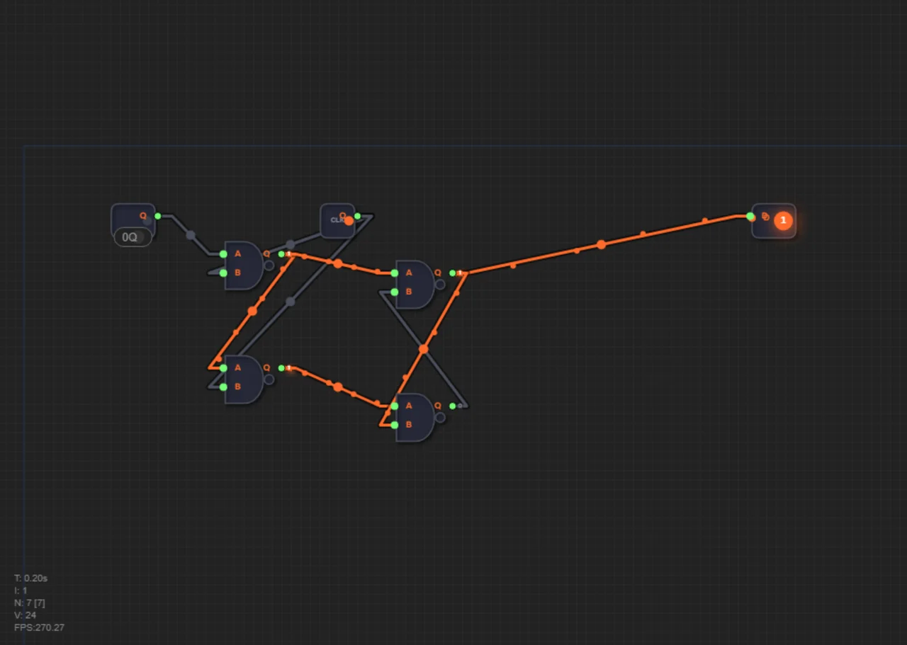
The DFF (D Flip-Flop) is a "smarter" version of the SR latch from the article about the magic of feedback. It has two inputs: D (data) and Clock. At the moment of the edge (Clock transitioning from 0 to 1) it captures the value on D and holds it until the next edge. Between edges, the flip-flop ignores any noise on input D — this is exactly what distinguishes it from the "transparent" latch, which watches its input all the time.
In the game the DFF is built in the master-slave configuration from four NAND gates: the first pair (master) accepts data when Clock=1, and the second pair (slave) stores it when Clock=0. The output always shows the stable value written at the last edge. A ready clock generator is already placed on the level — all that's left is to connect it to the flip-flops.
The behavior table of the D flip-flop
| D before the edge | Clock edge | Q after the edge |
|---|---|---|
| 0 | 0→1 | 0 |
| 1 | 0→1 | 1 |
| Any | No edge | Q unchanged |
The first two rows are writing a bit on the edge. The third row is the most important one: without an edge, nothing happens. No matter how "dirty" a signal arrives at D between ticks, the output stays the same.
Three ticks on the timeline
Let's trace the flip-flop on a timeline of three ticks, writing the bits 1, 0, and 1.
1. Before the first edge we set D=1. At the moment of the 0→1 transition the flip-flop captures a one: Q=1.
2. Between ticks the signal "wanders": D jumps 0→1→0. It's noise, but there is no edge — and Q stubbornly stays 1.
3. Before the second edge D=0. On the edge the flip-flop writes 0: Q=0.
4. Before the third edge D=1. On the edge Q becomes 1.
At the end of the timeline the flip-flop holds the last written value — 1. We wrote three bits in three ticks, and no noise spoiled a single one. Now connect several flip-flops to a shared Clock — and you get an honest register, described in the article "Registers: First Byte of Memory".
Common mistakes
- Connecting D but forgetting Clock: without edges the flip-flop will never capture data.
- Feeding data to the Clock input instead of D: ticks must come from the clock generator, not from a random signal.
- Changing D at the same moment as the edge: at the 0→1 transition the flip-flop must see a stable value.
Summary
1. Combinational circuits work instantly, but memory needs time — it needs a shared rhythm.
2. The clock generator emits a regular 0→1→0 pulse; a gigahertz frequency means billions of ticks per second.
3. The D flip-flop captures the D input only on the Clock edge (the 0→1 transition).
4. Between edges the flip-flop ignores input noise — memory stays stable.
5. The DFF is built from four NAND gates in the master-slave configuration.
6. Several flip-flops sharing a Clock form a register.
In level 1.11 you will build a D flip-flop from four NAND gates in the master-slave configuration and connect it to the pre-placed clock generator. Remember: data is captured only on the rising edge of Clock.