Level 47: Create Computer
Task
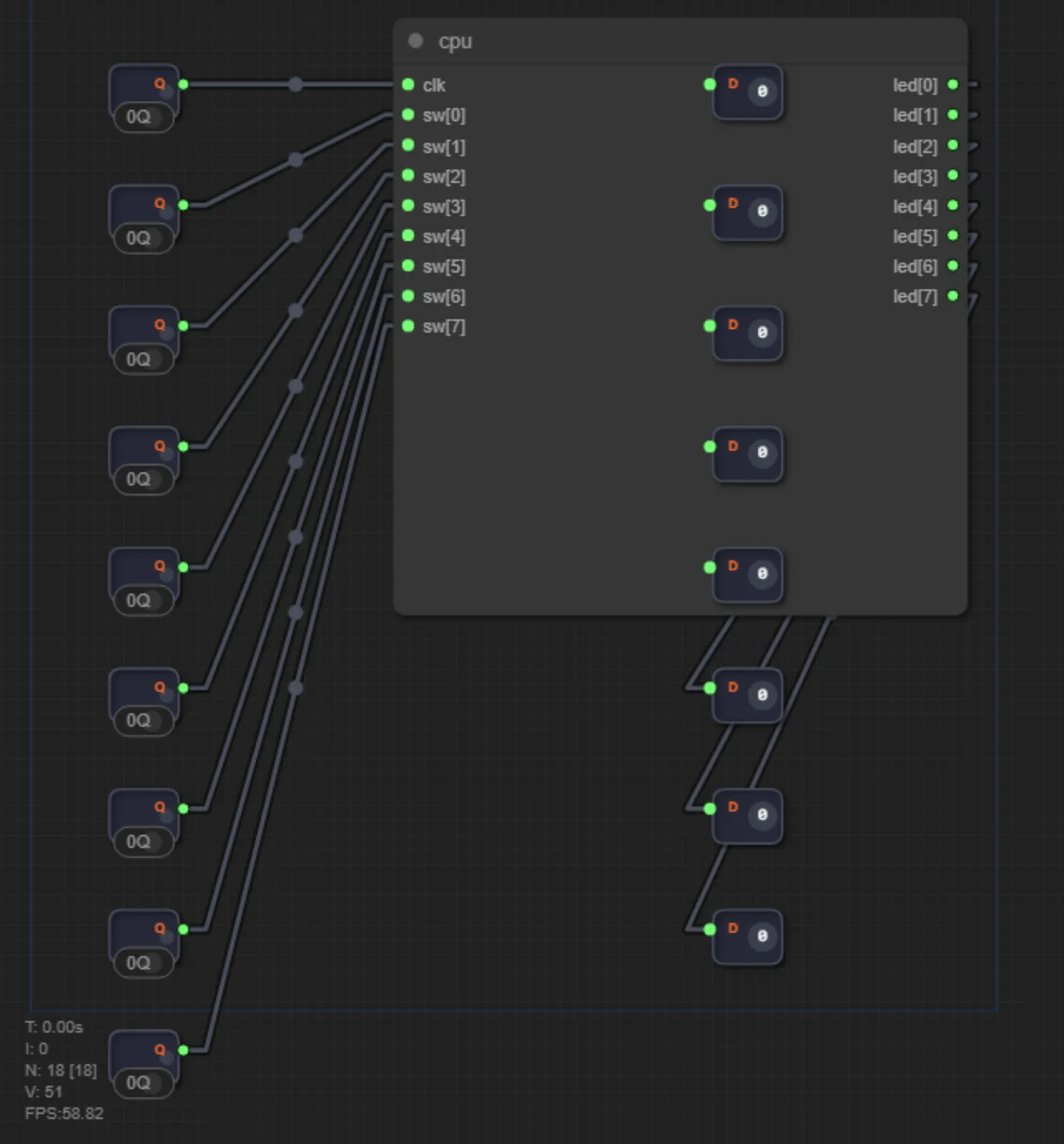
Final level! Write top.v — the top-level module that instantiates the CPU and connects it to the physical ports of the Tang Nano 9K board.
The project contains several files (tabs on the left):
top.v— editable: your top-level module.cpu.v— read-only: Counter8 → ROM → Reg8 (simplified processor).counter8.v,adder8.v,full_adder.v,reg8.v— read-only: standard building blocks.
Top interface: clk (clock), top_sw[7:0] (switches), top_led[7:0] (LEDs). Press «Build Computer» — the project assembles into a ZIP archive with Ershov_Computer.pins.cst for flashing to the Tang Nano 9K.
How to program the FPGA
Verilog code cannot be «run» like an ordinary program: it must be synthesized — turned into a configuration of the chip's logic cells — and then flashed into the FPGA's memory. Here is the full «browser to silicon» path.
What happens during synthesis? The compiler does not produce instructions — it maps your circuit onto the chip's resources: logic cells (LUTs) and programmable interconnects between them. The bitstream physically changes the die: interconnects are opened or closed, and your processor "grows" on the chip. That is fundamentally different from compiling C++: there a program is stored in memory and executed by a processor; here the circuit itself becomes the hardware.
Step 1. Get the project files
Press «Build Computer» on level 47. You will download Ershov_Computer.zip:
top.v,cpu.v,counter8.v,adder8.v,full_adder.v,reg8.v— the source files of your computer;Ershov_Computer.pins.cst— the physical constraints file: port-to-pin mapping is already done for you.
| Port | Tang Nano 9K pin | Connected to |
|---|---|---|
clk | 45 | Clock input (STEP button on the Ershov Board lab dock) |
top_led[7:0] | 10–17 | 8 LEDs |
top_sw[7:0] | 20–27 | 8 switches |
Step 2. Prepare the board
You need a Sipeed Tang Nano 9K dev board (chip GW1NR-9) and a data-capable USB-C cable. No external programmer is required: the board has a built-in USB-JTAG programmer. Connect the board to your computer via USB.
If you use the Ershov Board lab dock — seat the Tang Nano 9K module into its 2×24-pin socket; the switches and LEDs are then wired to the chip per the table above.
Step 3. Choose a flashing method
Option A: Ershov Loader — one button (recommended)
The project's utility hides all the EDA complexity: open Ershov_Computer.zip in it and press «Flash chip». It then:
- Unpacks the archive and validates the files;
- Runs synthesis and place & route via the Gowin console engine (
gw_sh); - Flashes the board via
openFPGALoader -b tangnano9k; - Shows your CPU's stats: how many LUTs and flip-flops it occupies on the chip.
The utility is described in the Ershov Board — Technical Specification article.
Option B: Gowin IDE (official environment, manual)
- Download Gowin EDA from the vendor's site (the Education version is free, the license arrives by e-mail) and install it.
- Create a project:
File → New Project→ project name → in the Device field selectGW1NR-LV9QN88PC6/I5(that is the Tang Nano 9K chip). - Unpack
Ershov_Computer.zipand add all six.vfiles to the project (right-click the Design tab →Add Files). - Make sure the top module is
Top(right-clicktop.v→Set as Top Module). Verilog is case-sensitive: the name in the project settings must match the module name in the code letter for letter. If the file saysmodule top, the project must saytop— otherwise the compiler throwsmodule not found. - Add the constraints file: right-click the Constraints tab →
Add Files→ pickErshov_Computer.pins.cst. - Build with the Run All button (or step by step: Synthesize → Place & Route).
- Connect the board via USB and open Programmer →
Program/Configure. If the board appears in the device list — hit program; flashing takes a couple of seconds.
Option C: command line
Synthesize via a TCL script, flash with the open-source utility:
gw_sh build.tcl                        # synthesis + place & route
openFPGALoader -b tangnano9k impl/pnr/project.fs   # flash over USB
Step 4. What you will see
Right after flashing, the computer comes alive: a «scanner» light runs across the top_led LEDs — the ROM is preloaded with the Knight Rider program, and on every clock tick the CPU outputs a new value to the LEDs. Clock it with the STEP button (slowly, one tick at a time) or from an oscillator. The top_sw switches feed data into the CPU's sw input.
Important: by default the bitstream is loaded into the chip's internal SRAM and lives until power is removed. Pull the USB cable and the computer "forgets" everything. That is the normal debug mode: flashing is instant and does not wear out the flash memory. To make the computer survive a power cycle, program the board's external SPI flash instead: in Gowin Programmer pick the External Flash mode, or add the -f flag on the command line: openFPGALoader -b tangnano9k -f project.fs.
This is the very computer you built across levels 1–47 — now running in real silicon instead of the simulator.
Troubleshooting
- The board does not appear in Programmer. Check that the USB cable carries data (not «charging only»); on Linux add udev rules for the programmer; on Windows install the USB-JTAG driver if needed.
- The board shows up in Gowin Programmer but not in openFPGALoader (Windows). The official Gowin programmer and openFPGALoader use different drivers for the same USB-JTAG interface. Installing Gowin IDE makes Windows adopt the official driver, and openFPGALoader (Options A and C) stops seeing the board. Fix it with the Zadig utility: select the Tang Nano 9K device and replace the driver with WinUSB. After that openFPGALoader sees the board again, but Gowin Programmer no longer does — the drivers take turns, so switch between them depending on the flashing method you use.
- «Module not found» synthesis error. Not all
.vfiles were added to the project — make sure there are six of them. - LEDs stay dark. Check that the
.cstfile is attached to the project and the top module is namedTop. - LEDs «flicker» when pressing STEP. The button must have hardware debouncing (RC network + Schmitt trigger) — see the Ershov Board requirements.
Related materials
- Ershov Board — Technical Specification — the board, pin mapping, Ershov Loader
- Control Unit — instruction decoder
- Module Hierarchy — multi-file projects
Solution for self-check
Try building the circuit yourself first. The solution below is a way to check yourself if you're stuck or have already solved it.
The Top module is extremely simple — just instantiate the CPU and wire the ports:
module Top(
    input wire clk,
    input wire [7:0] top_sw,
    output wire [7:0] top_led
);
  CPU cpu(clk, top_sw, top_led);
endmodule
Then press «Build Computer». The generated ZIP includes:
- All project files (
top.v,cpu.v,counter8.v,adder8.v,full_adder.v,reg8.v) Ershov_Computer.pins.cst— physical constraints: port-to-pin mapping for Tang Nano 9K (clk → 45, LEDs → 10–17, switches → 20–27)
The ZIP is ready to be flashed onto the real board. The full step-by-step «browser to silicon» walkthrough is in the «How to program the FPGA» section.