Level 16: Program Counter
Open the level →Where it fits in the machine →
Task
Goal: build a Program Counter (PC): a register + an ALU (or your ADDER8 chip); each clock tick increments the address by 1.
The Program Counter (PC) is the heart of the processor execution cycle. It holds the current instruction address and automatically increments it by 1 on each clock tick.
The main idea: the program counter closes the register → ALU → register loop: the adder increments the address, and it returns to the register. With this, part 1 has all its building blocks: gates, adders, ALU, memory, clock.
Path to this level
The competencies this level develops and their formation levels.
Related Materials
- Register8: counter component
- ADDER8: PC increment
- ProgramCounter
- How a Processor Works: From Transistor to Program
Solution for self-check
Try building the circuit yourself first. The solution below is a way to check yourself if you're stuck or have already solved it.
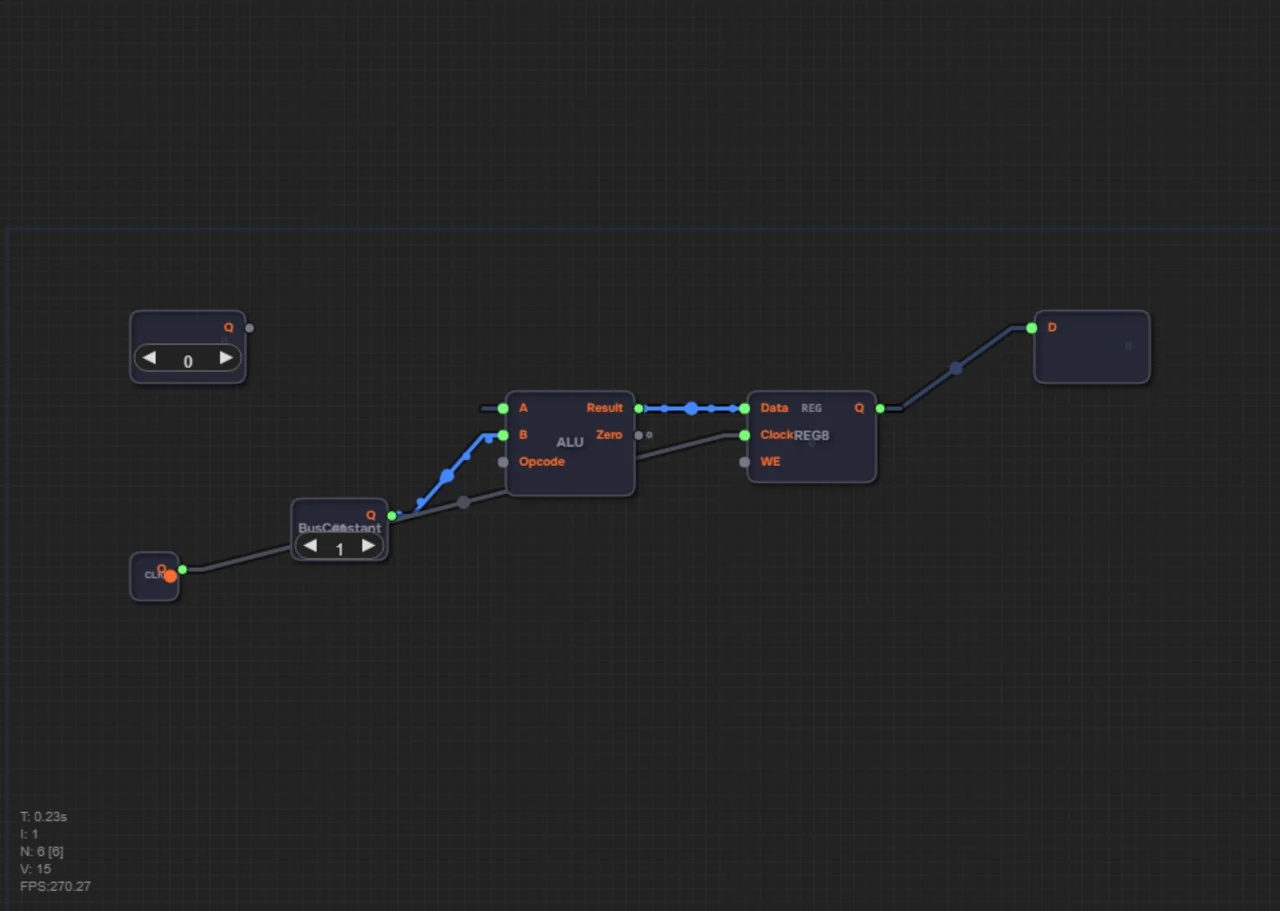
What you should get: the address is stored in the register, the adder increments it by 1, and the new value returns to the register on the clock edge: 0→1→2→3…
The circuit is a two-element loop:
- Place ALU8 and Register8.
- Feed Register8 output (Q) to ALU input A — this is the current address.
- Feed BusConstant set to 1 (already on canvas) to ALU input B — this is the increment (+1).
- Feed ALU output (Result) back to Register8 Data input — so the new value (address+1) enters the register on the next tick.
- Connect the Clock signal (already on canvas) to Register8 Clock input.
- Also connect Register8 output (Q) to the Addr output.
Leave the WE (Write Enable) pin of the register unconnected: WE = 1 — the register stores the new value on the clock edge, WE = 0 — it ignores the tick and keeps the old value. An unconnected WE counts as always 1, write is enabled.
Why D flip-flops in the register (level 11) and not transparent latches (level 10)? While the tick holds high, the register output would loop straight back into the adder input — during one long tick the address would race around the cycle many times (a race). A D flip-flop captures its input only at the clock edge, so the PC adds exactly +1 per tick.
Check yourself
What to feed the adder's second input — and why not the clock signal?
The constant 1: each tick the address grows by one. The Clock sets the moment of writing, not the step size.