ALU: The Heart of Your Processor
Up to this point, we've been doing fairly simple things: learning to add binary numbers. First one bit (HalfAdder), then three (FullAdder), then a chain of eight (Ripple Carry Adder). All this time we were moving toward one goal: learning to do a + b in hardware.
But a processor is not just addition. It needs to subtract, compare, perform logical operations (AND, OR, XOR), and much more. The question is: how do you fit all this math into one compact block that understands different commands?
The answer is called the ALU — Arithmetic Logic Unit.
The ALU Is Not One Calculator — It's Many Calculators in One
Here lies the main insight that many programmers misunderstand. When you write if (a > b) ... in code, the processor doesn't "think": "now I need to compare a with b, let me turn on the comparison block". No. Everything works completely differently.
Inside the ALU, all operations are performed simultaneously. Always. Every clock cycle. Without exceptions.
Imagine a factory conveyor where 8 machines work in parallel. Machine №1 stamps a part, machine №2 drills a hole in it, machine №3 cuts a thread. All the machines work simultaneously. At the end of the conveyor stands a sorter that takes only the needed part and throws away the rest.
The ALU works the same way. Inside it, in parallel, an adder works (computes a + b), a subtraction block (via two's complement), AND, OR, XOR, NOT blocks. All of them simultaneously receive the same input numbers a and b. All of them simultaneously compute their results. And then a multiplexer, controlled by the operation code (op_code), selects one of these results and sends it to the output.
The Operation Code: The Conductor of the Orchestra
How does the ALU know exactly what to do this cycle? It needs a control signal — the operation code (op_code). It's simply a number (usually 3-4 bits) that tells the multiplexer: "select output number N".
000 → a + b    (addition)
001 → a - b    (subtraction)
010 → a & b    (AND)
011 → a | b    (OR)
100 → a ^ b    (XOR)
101 → ~a       (NOT)
110 → a        (pass A)
111 → b        (pass B)
Anatomy of an 8-bit ALU
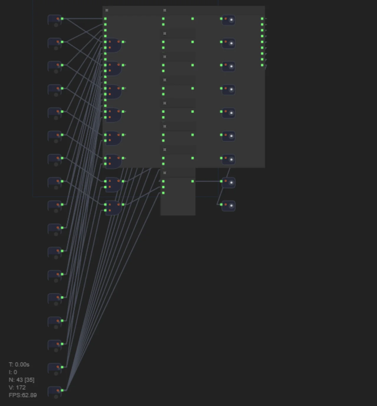
An adder, AND, OR, XOR, NOT — all work in parallel. An 8:1 multiplexer selects which result goes to the output.
Notice: in the circuit there is no logic like "if op_code = 000, turn on the adder, and if 010 — turn on AND". All blocks are always on. It's just that of the eight results, only one reaches the output. The other seven "hang in the air" — they exist, but nobody reads them.
Addition and Subtraction: Two in One
Here we use a trick from binary arithmetic: a - b = a + (~b + 1). It's called two's complement.
To get a negative number in binary, you need to invert all the bits of the number and add 1.
Check: 5 - 3 = 2. In two's complement: 5 + (~3 + 1) = 5 + (11111100 + 1) = 5 + 11111101 = 1 00000010 = 2 (dropping the most significant carry).
Writing the Verilog
For an ALU there's a concise way — describe the behavior in always style with case:
module ALU8(
    input  [7:0] a,
    input  [7:0] b,
    input  [2:0] op_code,
    output reg [7:0] result,
    output           zero
);
    always @(*) begin
        case (op_code)
            3'b000: result = a + b;
            3'b001: result = a - b;
            3'b010: result = a & b;
            3'b011: result = a | b;
            3'b100: result = a ^ b;
            3'b101: result = ~a;
            3'b110: result = a;
            3'b111: result = b;
        endcase
    end

    assign zero = (result == 8'b0);
endmodule
Let's go through it line by line:
output reg [7:0] result—regmeans the variable will be written inside analwaysblock.always @(*)— "run this block every time at least one signal on the input changes".case (op_code) ... endcase— the analogue of switch/case from C.assign zero = (result == 8'b0)—zerowill be 1 if the result equals zero.
This code is concise, but under the hood the synthesizer will turn it into exactly the circuit we described: parallel compute blocks + a multiplexer.
Parallelism in Action: Why It's Fast
The ALU receives op_code = 000, and the addition result appears at the multiplexer's output. All this takes one clock cycle (plus the signal propagation delay).
Now imagine the ALU were designed "economically" — like in software: check op_code, and only then turn on the needed block. That would require extra cycles for switching. That's exactly what doesn't happen. Everything is computed at once, and the multiplexer simply "filters out" the unnecessary.
Summary
1. ALU is a set of parallel compute blocks (an adder, AND, OR, XOR, etc.), whose result is selected by a multiplexer according to the op_code signal.
2. In Verilog, an ALU can be described behaviorally via always @(*) case, and the synthesizer will build the needed structure itself.
3. Parallelism is not an optimization but a fundamental property of silicon. All operations are computed simultaneously, always.
In level 36 you will build an 8-bit ALU supporting two operations: addition (ADD) and bitwise AND. Use the Adder8 module from the previous level, multiplexers, and AND gates. This is the final challenge of the Verilog cycle — after it, you'll be able to say that you designed the heart of a processor with your own hands.