Tang Nano 9K: From ZIP Archive to a Living Board
The final level of the course — "Create a Computer" — ends with a special button: "Create Computer". It packs your Verilog project into a ZIP archive ready to load onto a real FPGA board, the Tang Nano 9K. This article maps the path from the archive to running lights on hardware: what an FPGA is, how GOWIN IDE is organized, and what to do when something does not work.
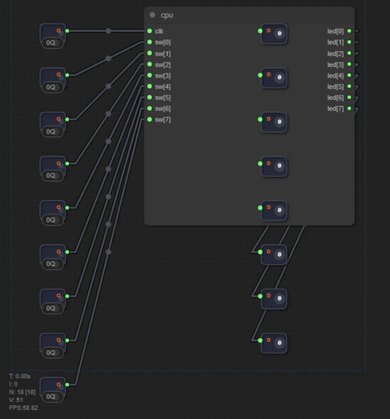
What an FPGA is and why it is not "firmware"
An FPGA (field-programmable gate array) is a chip whose millions of vacant transistor "tiles" can be assembled into almost any digital circuit. You described the circuit in Verilog — the vendor's tools (for the Tang Nano 9K it is GOWIN) will lay it out across the tiles and wire it inside the chip.
The key difference from a microcontroller: on an MCU your program runs on top of a fixed processor, while in an FPGA the processor itself is what you just built. The Tang Nano 9K is an inexpensive board on the GW1NR-9 chip: three onboard LEDs, a button, connectors for displays — a perfect first "silicon" step after the simulator.
Step 1. Exporting the ZIP from the simulator
On level 4.47, after passing, press "Create Computer" — the simulator packages the project: all Verilog files (top.v with your computer, memory, peripherals) and the pin constraints file Ershov_Computer.pins.cst, which already maps every signal to its board pin. Save the ZIP and unpack it into a folder with no non-ASCII letters or spaces in the path — GOWIN dislikes those.
Step 2. GOWIN IDE: project and synthesis
Download GOWIN IDE from the vendor's site (Sipeed/GowinSemiconductor, free registration) and install it. Then:
1. File → New Project, type FPGA Design, family GW1NR-9, chip GW1NR-LV9QN88PC6/I5 (as on the board).
2. Add Sources — add every .v file from the archive and the .cst constraints file.
3. Press Synthesis (the gear icon). The tool checks your Verilog and "folds" the circuit into a netlist. Errors here are the same as the red lines in the simulator: read the line numbers.
4. Place & Route — the layout of your circuit across the chip's physical tiles.
5. Generate the program: Process → Configure → build the bitstream (a .fs configuration file).
On a school laptop the whole path takes a few minutes. If synthesis complains about language support — make sure Verilog-2001 is selected (it is the default).
Step 3. Flashing the board
Connect the Tang Nano 9K over USB-C. In GOWIN open the Programmer (Tools → Program Device) — it will detect the board. Choose your .fs file, the SON: Flash mode (the image survives power-off) and press Program. A few seconds later the board reboots — and your processor, which existed only in a browser this morning, is ticking on real silicon: the LEDs blink with the program from ROM, the button works as an input.
If something does not work
— Synthesis fails: compare the code with the working simulator version. Frequent causes: behavioral constructs (always, if) accidentally left in the code, or module names not matching file names.
— The board is invisible in Programmer: install the USB driver from the GOWIN package; on Linux — the udev rules.
— The LEDs do not blink: check that the clock is wired to the right pin in the .cst (the export's constraints file already maps clk to pin 45) and that the ROM holds a program.
— The circuit works "almost correctly": recall the article on propagation delay — on real hardware the timing effects are even more visible than in the simulator.
Once the first processor comes alive on the board, you have walked the path digital engineers walk: idea → HDL code → simulation → synthesis → hardware. After that — only your own projects.
Test yourself
How is an FPGA different from a microcontroller?
In a microcontroller the processor is fixed and you write a program for it. In an FPGA you assemble the digital circuit itself — including a processor, if you need one.
Which file ends up loaded onto the board?
A bitstream with the .fs extension — an image of the FPGA's configured tiles and connections, produced after synthesis and place&route.
Why unpack the ZIP into a path without non-ASCII letters?
GOWIN tools are sensitive to path encodings: Cyrillic letters and spaces in folder names periodically break synthesis and file lookup.