Program Counter
When you read a book, you run your finger along the lines or use a bookmark so you don't forget where you stopped. The processor needs such a "bookmark" too: a program can consist of thousands of instructions stored in memory one after another.
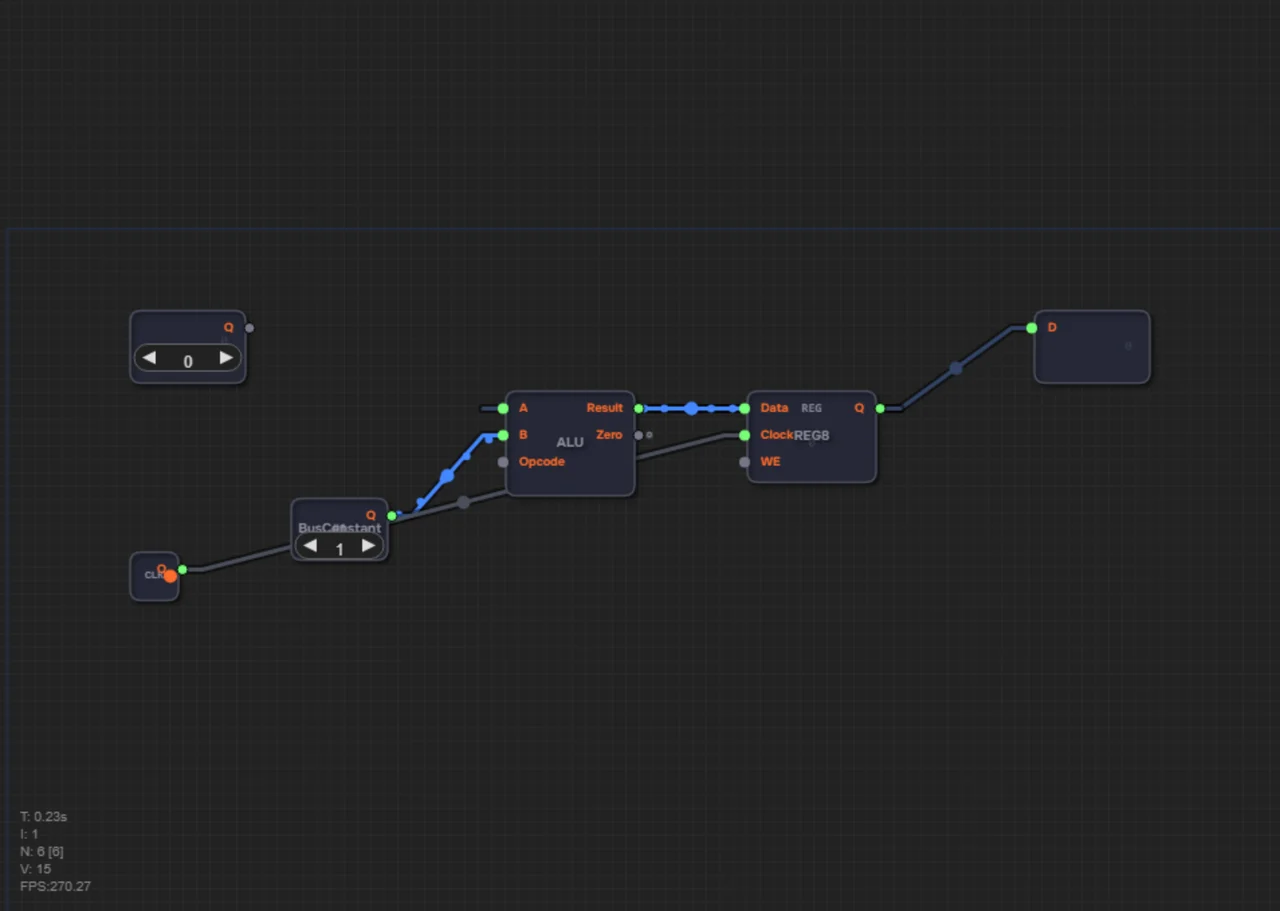
This role is played by the Program Counter (PC). It's a special register that always holds the address of the memory cell in ROM where the next instruction lives.
By default the Program Counter works very simply: after every processor tick it takes a step forward (adding +1 or +2 to its value). It read line zero — moved to line one, read line one — moved to line two. But sometimes a program needs to jump elsewhere (for example, when a loop starts). At that moment the processor sends the Program Counter a new address, overwriting its value, and code reading continues from a completely new place.
What the PC is built from
The Program Counter is made of familiar blocks connected into a ring: Register8 holds the current address, ALU8 adds 1 to it, and the result is written back into the register. Specifically: the register output Q goes to ALU input A — that's the current address; ALU input B receives a BusConstant set to 1 — that's the increment. The ALU output (Result) returns to the register's Data input, so on the next tick the register receives address+1. The Clock signal is connected to the register's Clock input — every edge moves the address forward.
The result is a "register → ALU → register" loop — the same pattern you've already seen in counters, except instead of a "+1" button a real adder circuit does the work. The register's WE input can be left unconnected: by default writing is enabled.
The PC points to the next instruction
Why increase the address at all? The instruction memory (ROM) stores instructions one after another, and the PC shows which ROM cell to read right now. The processor takes the instruction at the PC's address, executes it — and by then the PC has already grown and points to the next one. That's how a program executes step by step, automatically.
In our computer, instruction memory and data memory are separate — that's the Harvard architecture, covered in the article "Harvard Architecture". And the fetched instruction byte goes to the decoder: how it turns the code into control signals is described in the article "Instruction Decoder".
A trace: ADD 10, STA 20, HLT
Let's follow the Program Counter while a simple program runs: ADD 10, STA 20, HLT.
| Tick | PC | What the processor does |
|---|---|---|
| 0 | 0 | Reads ADD 10 from ROM[0] and executes it |
| 1 | 1 | Reads STA 20 from ROM[1] and executes it |
| 2 | 2 | Reads HLT from ROM[2] and stops |
Notice the third tick: HLT is the halt instruction. After it, execution stops and the PC no longer grows.
And what if JMP 0 stood in place of HLT? After executing it, the processor would force-write 0 into the PC, ADD 10 would run again — an infinite loop. The Program Counter and jump instructions are the foundation of every loop in programs.
Two-byte instructions: stepping by +2
In the byte format each instruction takes one byte, so the PC steps by +1. But in the word format an instruction consists of two bytes: byte 0 is the opcode, byte 1 is the operand (a number from 0 to 255). If the PC keeps stepping by +1, it will land in the middle of an instruction — on the operand byte — and the processor will treat data as a command.
That's why the ready ProgramCounter chip has an Inc input (port 4) — it defines the step size. By default, if the input is unconnected, Inc = +1. And on level 2.19 a BusConstant set to 2 is connected to this input — the PC starts stepping 0, 2, 4, 6…
A numeric example: two formats
Imagine a program of two instructions in word format: ADD 10 and HLT.
ROM[0] = the opcode ADD (0x10), ROM[1] = the operand 10, ROM[2] = the opcode HLT, ROM[3] = the operand (unused).
1. PC=0: the processor reads byte ROM[0] — the ADD opcode, then the next byte ROM[1] — the operand 10. It executes ADD 10.
2. The PC steps by +2: now PC=2. It reads ROM[2] — the HLT opcode. Stop.
In byte format the same two instructions would occupy ROM[0] and ROM[1], and the PC would step by +1: 0, 1. The only difference is the price: the PC step must match the instruction size, or the processor will read an operand as a command.
Common mistakes
- Not feeding the ALU result back into the register: without the feedback loop the address won't grow.
- Connecting Clock to ALU input A instead of the register's clock input — the register is what must be clocked.
- Forgetting the Inc input on level 2.19: without the constant 2, the PC will read the middles of instructions.
Summary
1. The PC is a register that holds the address of the next instruction.
2. It's built from Register8 + ALU8 + the constant 1 in a "register → ALU → register" loop.
3. Each tick increases the address by the step size: +1 in byte format.
4. The JMP instruction overwrites the PC with a new address — that's how loops and branches work.
5. In word format an instruction takes two bytes, so the constant 2 is fed to the Inc input, and the PC steps 0, 2, 4, 6…
6. If the step doesn't match the instruction size, the processor reads garbage.
In level 1.16 you will build a program counter from a register, an adder, and the constant 1, and in level 2.19 you'll connect the constant 2 to the Inc input so the PC steps through two-byte instructions.