Logic Gates — AND, OR, NOT
If zeros and ones are the alphabet of a computer, then logic gates are its rules of grammar. A gate is a tiny electronic circuit that takes one or more input signals and produces an output according to strict rules.
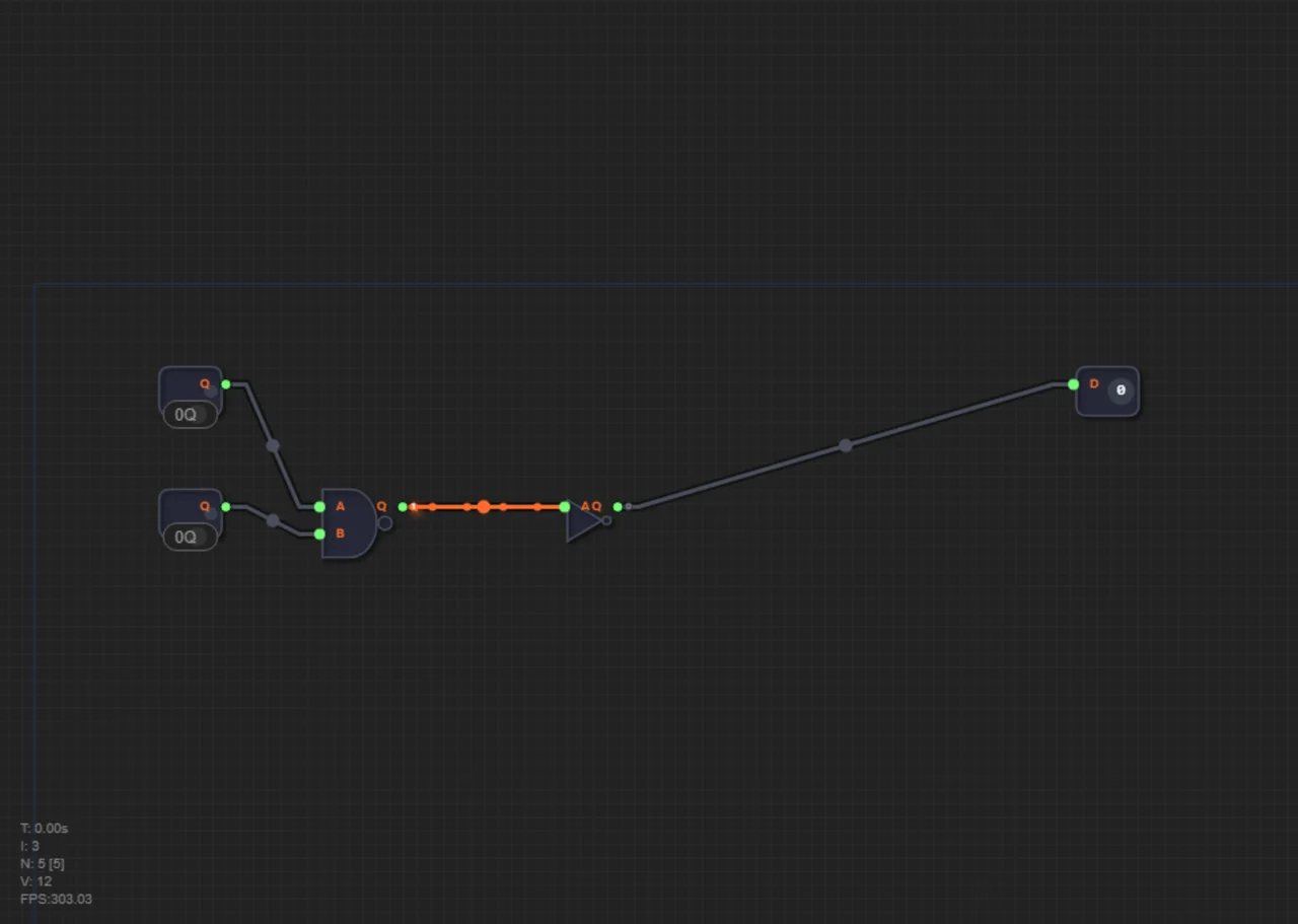
There are only three basic gates — NOT, AND, and OR. Memorize their truth tables, because every digital circuit, no matter how complex, is assembled from these three rules.
The NOT gate — the electronic rebel
NOT always does the opposite. Feed it a 1 (current flowing) — it outputs a 0 (no current). Feed it a 0 — it outputs a 1. In circuit design it's often called an inverter: it "flips" the signal.
The truth table of the NOT gate:
| Input | Output |
|---|---|
| 0 | 1 |
| 1 | 0 |
The AND gate — the strict security guard
AND is a strict security guard who demands all passes at once. It outputs a 1 only when ALL of its inputs are 1. If even one input is 0, the output is also 0.
For two inputs this looks like: 00 → 0, 01 → 0, 10 → 0, and only 11 → 1.
The OR gate — the friendly gatekeeper
OR is the friendly gatekeeper. It's enough that at least one condition is met. It outputs a 1 if current is present on the first input, the second input, or both. It outputs a 0 only when nothing arrives on any input.
For two inputs: 00 → 0, 01 → 1, 10 → 1, 11 → 1.
One table for NOT, AND, and OR
Let's put all three gates in one table:
| A | B | NOT A | A AND B | A OR B |
|---|---|---|---|---|
| 0 | 0 | 1 | 0 | 0 |
| 0 | 1 | 1 | 0 | 1 |
| 1 | 0 | 0 | 0 | 1 |
| 1 | 1 | 0 | 1 | 1 |
Notice the pattern? AND and OR agree almost everywhere and differ in only one row: on inputs 01 and 10, AND outputs 0 while OR outputs 1. AND is stricter, OR is more generous.
NAND — the universal gate
In the game you don't start with ready-made AND, OR, and NOT gates. At the very beginning you only have a wire and the NAND gate — "NOT-AND", which outputs 0 only when both inputs are 1. NAND is remarkable because any other gate can be built from it:
• NOT: tie both inputs of a NAND together — in level 1.2 you build the inverter exactly this way.
• AND: take a NAND and put an inverter after it (NAND + NOT) — that's how level 1.3 is built.
• OR: put inverters on both inputs of a NAND — the De Morgan's laws explain why, and level 1.4 tests it in practice.
Real-life examples: doors, ATMs, and alarms
Imagine an automatic supermarket door. It should open if the motion sensor is triggered OR the button is pressed. Let A = motion sensor, B = button. If A = 1 (someone approached) and B = 0 (the button wasn't touched), the OR gate outputs 1 — the door opens.
But an ATM dispenses cash only if a card is inserted AND the correct PIN is entered. If A = 1 (card in place) but B = 0 (wrong PIN), the AND gate outputs 0 — no cash.
The NOT inverter is useful for an alarm: it should go off when the door is NOT closed. Door closed (signal 1) → NOT outputs 0 → the alarm stays silent. Door open (signal 0) → NOT outputs 1 → the alarm triggers. All "smart" electronics around us are built from these three operations.
Common mistakes
• Mixing up AND and OR: AND demands all ones, OR just at least one.
• Forgetting that NOT turns 0 into 1, not 0.
• Thinking that 11 → 0 for OR: no, OR outputs 1 on two ones as well.
You can verify any gate combination in the truth table generator: type a formula and get the full table for every input combination.
Test yourself
What does a NOT gate do?
It flips the signal: 0 becomes 1 and 1 becomes 0.
What does an AND gate return for inputs 1 and 0?
0. AND outputs 1 only when both inputs are 1.
Why is NAND called the universal gate?
Any other gate — NOT, AND, OR — and in fact any circuit at all can be built from NANDs alone.
Summary
1. NOT is the inverter: 0 → 1, 1 → 0.
2. AND outputs 1 only when all inputs are 1.
3. OR outputs 1 if at least one input is 1.
4. NOT, AND, and OR can all be built from the universal NAND gate.
5. Gates are the grammar of a computer: complex logic is born from simple rules.
In levels 1.2–1.4 you will build all three gates from a single NAND: in level 1.2 — the NOT inverter (by tying both NAND inputs together), in level 1.3 — the AND gate (NAND + inverter), and in level 1.4 — the OR gate using De Morgan's law. To learn more about the binary alphabet, read "0 and 1: The Language Machines Speak".