Learn Assembly from Scratch: 15 Instructions and a Training Emulator
Why assembly looks hard
Assembly has a reputation as a subject for the chosen few. Textbooks teach it through x86: multi-volume manuals, registers with names like EAX, dozens of addressing modes, files, linkers and directives like section .data. That toolset is real, and drivers and kernels are written with it. None of it has anything to do with the idea of assembly itself.
The idea fits in one paragraph. The processor reads a number-instruction from memory, executes it, and moves to the next one. Addressing modes, pipelines and caches are additions layered on top of that model over decades of compatibility with older processors. Remove the legacy, keep the model, and learning becomes manageable: that is exactly what a training emulator does.
We covered what assembly reveals about familiar high-level languages in the article "Assembly: The Most Honest Programming Language". This one is a practical route: where to start, in what order to move, and which tools you need.
What a training emulator gives you
For learning to move forward without dead ends, a training emulator needs four things:
- A tiny instruction set. Fifteen instructions fit on one screen; x86 has hundreds of base instructions, and thousands with the extensions.
- Visible registers. The program counter, the accumulator and the flags are on screen and change before your eyes.
- Single-stepping. You can pause the program after any instruction and inspect what changed.
- Help at the moment of execution. A hint explains the current instruction right above the code, with no detour to the documentation.
The Ershov Computer emulator
The emulator runs in the browser and requires nothing to be installed: no compilers, no virtual machines, no accounts. The processor is 8-bit with a Harvard architecture: instructions and data live in separate memories, ROM for instructions and RAM for data, 256 cells each.
The processor does not come pre-assembled: on levels 16–18 you build it yourself from the blocks you already have, from the adder to the instruction decoder. After that, assembly stops being an abstraction: an LDA instruction physically passes through the decoder and the buses you wired with your own hands.
Instructions come in two encodings. In the byte format the whole instruction fits in one byte: the top four bits store the opcode, the bottom four the operand, from 0 to 15. In the word format (it opens at level 19) an instruction takes two bytes, and the operand grows to 0–255.
The logic simulator the whole game grows from is available separately: /en/tools/logic-simulator/. To start playing: /en/learn/.
A first program: three actions and a stop
Here is a program that fits in four lines:
LDA 7      ; ACC = 7 — load the number 7 into the accumulator
ADD 0      ; ACC = ACC + RAM[0]
STA 0      ; RAM[0] = ACC — store the sum
HLT        ; halt the processor
The program adds the number 7 to the contents of memory cell zero and writes the sum back. Type it into the debugger: open the sandbox with a ready processor, this listing will already be in the editor, and press Step. The same processor is assembled on level 25, "Negative Check".
After the first step the register row changes: PC = 02 (in the word format every instruction takes two bytes), ACC = 7, and the Z and N flags are still zero. The line above the code explains what just happened: "LDA 7: ACC 0 → 7". RAM is still all zeros: the program has not reached STA yet.
The debugger as a training ground
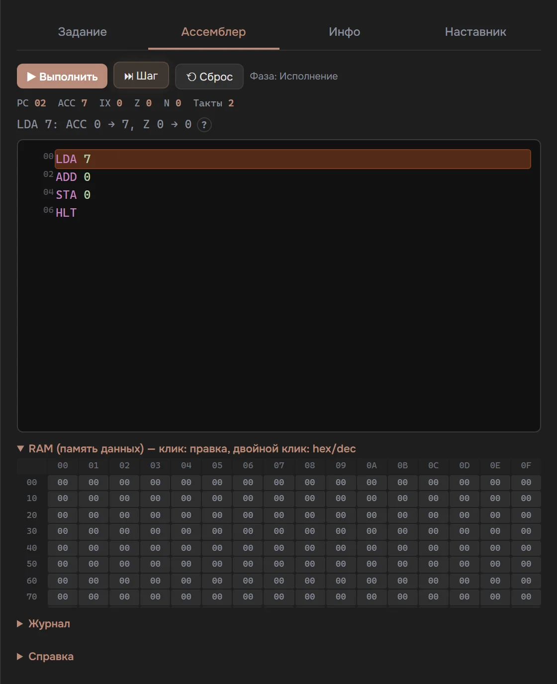
The debugger turns program execution into something you can watch. The Step button executes one instruction, and the phase indicator shows where the processor is: on "Fetch" it reads the instruction from ROM, on "Execute" it performs it. The register row gathers the whole state in one place: PC, the accumulator ACC, the index register IX, the Z and N flags, and the cycle counter.
To the left of every line of code stands its address in ROM in hexadecimal: 00, 02, 04. Clicking an address sets a breakpoint: the auto-run will stop right before that instruction. In a long loop this is how you reach the interesting spot without clicking Step a hundred times.
The expanded RAM block shows all 256 cells in hex. Clicking a cell opens editing, double-clicking switches the cell format between hex and dec, and modified cells are highlighted.
The live hint occupies the line between the registers and the code. Before the run it explains what the current instruction will do; after a step it shows the result with "before → after" values. The "?" icon next to it opens a glossary entry for the instruction. You will not need to look up mnemonics in documentation: the answer sits one line above the code.
The learning route
The game introduces instructions gradually, and the order is worth keeping: each one builds on the previous.
- Arithmetic and memory. LDA, ADD, STA: load, add, store. The first programs of part 2 are built on this trio.
- Branches and loops. JMP and the conditional jumps JZ and JN are the basis of all logic; the article "Branching and Loops" walks through them with examples.
- The Z and N flags. Conditional jumps rely on the ALU flags; how the processor learns about zero and negatives is covered in "Processor Status Flags".
- Pointers. The index register IX and the instructions LDX, LDAX, STAX, INX open up indirect addressing, arrays and strings; details in "Pointers and Index Registers".
- Memory and ports. The same address can point to a RAM cell or to an input/output device; "Memory-Mapped I/O" tells how that works.
- The gamepad and Snake. On level 23 the program reads buttons for the first time, and on level 29 a full game comes together from instructions — the final exam of part 2.
The opcodes of all fifteen instructions and the syntax rules are collected in the assembler manual; keep it at hand as a reference table. The course curriculum gives a time estimate for every level, so you can gauge how long the whole route will take.
Common mistakes
1. Confusing a number with an address. LDA 7 loads the number 7 itself. ADD 0 adds the contents of cell 0, and that cell can hold anything. The first strange results almost always come from here.
2. Exceeding the operand range. In the byte format the operand is 0–15: the high bits are dropped without warning, so LDA 42 turns into LDA 10. Numbers above fifteen need the word format.
3. Forgetting HLT. Without a halt instruction the processor keeps reading past the end of the program: zero bytes execute as NOPs, then the counter overflows and the program starts running again from the beginning.
FAQ
How many instructions does the training assembly have?
Fifteen: arithmetic (ADD, SUB, AND, OR), memory access (LDA, STA), jumps (JMP, JZ, JN), the index register (LDX, LDAX, STAX, INX), NOP and HLT. The full table with opcodes lives in the assembler manual.
Do I need to install anything?
No. The emulator and the debugger run in the browser, and progress is stored locally. There are no compilers to download and no environment to set up.
How is the training assembly different from a real one?
The training processor executes instructions through the same fetch-and-execute cycle as industrial x86 or ARM chips; the concepts of registers, flags, jumps and indirect addressing are the same. The difference is scale: x86 carries thousands of instructions and addressing modes accumulated over decades of compatibility, while the training processor fits into fifteen instructions, each visible in the circuit you built. The basic ideas transfer directly: the syntax and the tooling change, the model stays.
How long does it take to learn?
It depends on your background and pace. The course curriculum gives a time estimate for every level: the first assembly programs come after the processor is built (levels 16–18), and the final Snake closes level 29.
Test yourself
How does the operand of LDA differ from the operand of ADD?
LDA takes an immediate value: LDA 7 puts the number seven into the accumulator. ADD reads data at an address: ADD 7 adds the contents of cell 7 (or of the port with the same number).
What happens without HLT?
The processor keeps reading past the end of the program. Zero bytes execute as NOPs, and after the end of memory the counter overflows and the program starts over.
Why do we need the Z and N flags?
The ALU sets them after every operation: Z signals a zero result, N a negative one. The jumps JZ and JN look at the flags and decide whether to continue in order or jump to the address in the operand. Every branch and loop rests on them.
What you can do today: open the sandbox with the processor and type the four-line program above. Building the processor with your own hands comes later, on levels 16–18. Every one of its instructions is visible both in the code and in the circuit, and the result stays in RAM[0], where you can see it with your own eyes in the debugger.