Pointers and Index Registers
Suppose we need to move our Snake's tail, which occupies 10 memory cells. With ordinary instructions (direct addressing) you'd have to write a separate line for every cell: read cell 1, write to 2, read 2, write to 3... It's terribly inconvenient, and if the snake grows to 100 cells, the code simply won't fit in memory!
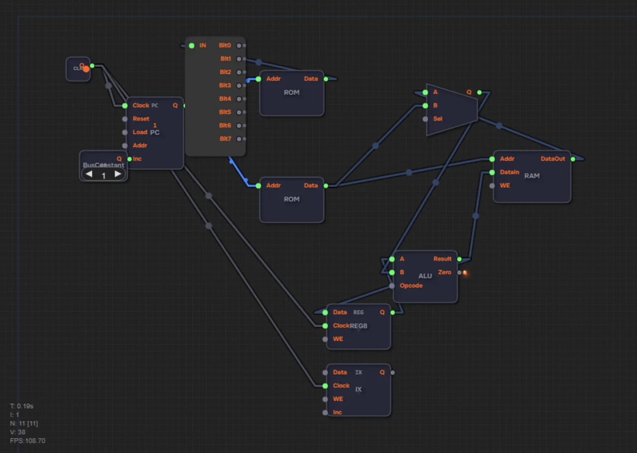
To work with arrays of data, engineers came up with indirect addressing and the Index register (IX). Unlike ordinary instructions that are hardwired to one specific address, the IX instructions use it as a pointer.
It's like a slider on a ruler: you hold your finger at mark 50, move it to 51, 52 — and each time you say: "work with the place where my finger is right now."
What indirect addressing is
Direct addressing: STA 50 — address 50 is written right into the instruction. Indirect addressing: STA [IX] — the address lives in the IX register, not in the command. The processor reads the number in IX and works with that cell.
The assembler translates STA [IX] into the STAX instruction (opcode 11) and LDA [IX] into LDAX (opcode 10). The brackets are a convention meaning "take the address from the register." We covered the instruction set in the article about assembly. You can try indirect addressing in the sandbox with a ready processor: LDX, STAX and LDAX are fully wired there.
Index register instructions
| Instruction | Opcode | Effect |
|---|---|---|
| LDX N | 9 | IX = N — load an address into the pointer |
| INX | 13 | IX = IX + 1 — move the pointer forward |
| LDA [IX] | 10 (LDAX) | Acc = RAM[IX] — read through the pointer |
| STA [IX] | 11 (STAX) | RAM[IX] = Acc — write through the pointer |
Just four instructions — and the entire memory array is in your hands.
The pointer, in numbers
Let IX = 50. The instruction STA [IX] writes the accumulator into RAM[50]. Then INX — and IX = 51. Repeat STA [IX] — the data lands in RAM[51]. Four steps — set the pointer, write, shift, repeat — and you've walked through all of memory without writing a single concrete address in the code.
How the address is selected in hardware
The RAM address is chosen by a BusMUX: one input receives the operand from the ROM, the other receives the IX register's output (IX.Q). The decoder's UseIX signal switches between them. For an ordinary instruction the ROM operand is used; for LDAX or STAX the value of IX is used.
One device, two address sources, one switch. On level 2.21 you wire your first BusMUX and meet the index register — in the finished computer, a multiplexer like this selects the RAM address source.
Why does this need a separate register instead of the accumulator? The accumulator has its own job: it holds computation results and the CPU constantly overwrites them. IX is free of that duty — it keeps the address at all times while the accumulator works with numbers. The roles never mix: one register computes, the other points to where to look.
Clearing 100 cells with three instructions
The classic example — zero out an array of 100 bytes. Instead of 100 STA instructions, three in a loop are enough:
LDX 0       ; IX = 0 — starting address
loop:
LDA 0       ; Acc = 0 — value to write
STA [IX]    ; RAM[IX] = 0 — clear the cell
INX         ; IX = IX + 1 — next address
; check whether we've passed 100 cells,
; and jump conditionally back to loop
Notice the rhythm: STA [IX] writes at the current address, INX shifts the pointer, and the loop repeats. The exit condition — checking "has IX reached 100" — and conditional jumps are covered in the article about branching and loops.
Common mistakes
1. Forgetting LDX before LDAX/STAX: the pointer contains garbage, and the data ends up who-knows-where.
2. Confusing LDAX with LDA: LDA [IX] reads through the pointer, it doesn't load a number.
3. Shifting the pointer before writing: STA [IX] first, INX after.
Summary
1. The IX index register is an 8-bit pointer to a memory cell.
2. LDX N sets the pointer; INX moves it forward by 1.
3. LDA [IX] and STA [IX] read and write at the address stored in IX (these are LDAX and STAX).
4. A BusMUX selects the address: the ROM operand vs IX.Q, switched by the UseIX signal.
5. One three-instruction loop clears a whole array — without pointers that would be hundreds of lines.
In level 2.21 you will wire your first BusMUX — it selects the ALU's data source (RAM or the instruction operand) — and set the program counter to step by +2. The address BusMUX described above appears in the pre-wired layout of the next levels, where LDAX and STAX start working at full strength.