Feedback Magic — The SR Latch
All the circuits we've built so far are combinational: their output depends only on the current inputs. Change the input and the output changes; remove the signal entirely and the circuit forgets everything. How do you make a wire remember even a single bit of information?
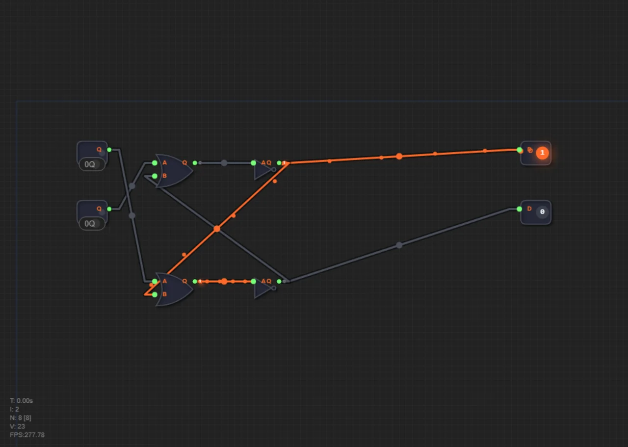
The answer is a brilliant engineering trick — feedback. What if you take a gate's output and wire it back to its own input? The signal starts running in a circle, sustaining itself! Every memory in every computer is built on it.
That's how the SR latch (Set-Reset) works. It has two inputs: one for setting (Set), one for resetting (Reset). Send a short pulse to Set, and the latch "clicks" and outputs 1 forever, even after the input signal disappears. It remembered a one! Pulse Reset and it resets to 0. This is the very first, tiny brick of memory in any computer.
Why ordinary circuits don't remember
All the circuits you've built so far — NOT, AND, OR, adders, multiplexers — are combinational: their output depends only on the current inputs. It has no state and no "history".
To run a program with dozens of steps, a computer needs something that saves the result of one step and feeds it to the next. It needs memory — an element whose output depends not only on the inputs, but on what happened before.
Feedback: a wire that talks to itself
The key trick is to feed a gate's output back to its own input. The game has no standalone NOR gate, but it's easy to build: OR output → NOT input. That's a NOR. Take two such NORs and cross-connect them: feed the first output (Q) to the second input of the second NOR, and the second output (NQ) to the second input of the first. The first inputs receive S and R. The circuit is described by two formulas: Q = NOR(R, NQ), NQ = NOR(S, Q).
Look carefully: each NOR has one input coming from its neighbor's output. When the first NOR outputs 1, that signal reaches the second NOR and holds its output at 0, and that 0 returns to the first NOR and keeps its 1 alive. A closed loop — a state that sustains itself.
The state table of the SR latch
| S | R | Q | What happens |
|---|---|---|---|
| 1 | 0 | 1 | Set — the latch remembers 1 |
| 0 | 0 | 1 | Holds — no inputs, the state stays |
| 0 | 1 | 0 | Reset — the latch remembers 0 |
| 0 | 0 | 0 | Holds — the state stays again |
The "Holds" rows are what make this a memory: when both inputs are 0, the output stays whatever the last Set or Reset left it as.
Step by step: how a 1 gets "stuck" in the circuit
Let's trace the latch on a concrete timeline.
1. Set S=1, R=0. The second NOR receives S=1 and resets NQ to 0. The first NOR sees R=0 and NQ=0 — both inputs are 0, so the output Q=1. The latch is set.
2. Remove both signals: S=0, R=0. The second NOR sees S=0 and Q=1, so its output NQ stays 0. The first NOR sees R=0 and NQ=0, so its output Q stays 1. The loop is closed: Q sustains itself.
3. Set R=1, S=0. The first NOR receives R=1 and resets Q to 0. The second NOR sees S=0 and Q=0, so its output NQ becomes 1.
4. Remove the signals again: S=0, R=0. The first NOR sees R=0 and NQ=1, so Q stays 0. The latch is reset and "frozen" again, this time at zero.
That's the whole trick: a 1 or a 0 gets "stuck" in the feedback loop and doesn't disappear until a reset command arrives. Earlier we saw how the ALU picks the right result with a multiplexer — now we've given that circuit memory.
One bit of memory
The SR latch stores exactly one bit — the value of Q. The second output NQ is always the opposite: Q=1 → NQ=0, Q=0 → NQ=1.
Practical example. The power button on your monitor is an SR latch in action. You press the button — a short pulse goes to Set, and the monitor turns on. You release the button — the contact opens, but the monitor keeps working because the latch "remembered" a one. Press again — the pulse goes to Reset, the latch clears, and the monitor turns off. Without feedback, electronics would have to hold the button down all the time.
Common mistakes
- Forgetting the cross-connections: two NORs placed side by side, without outputs fed back to inputs, have no feedback — and no memory.
- Not building NOR: the game has no ready NOR gate — remember it's OR + NOT.
- Expecting a change at S=0, R=0: in this state the latch doesn't change; it holds the previous value.
Summary
1. Combinational circuits have no memory: their output depends only on the current inputs.
2. Feedback — feeding an output back to its own input — creates a stable, self-sustaining state.
3. Two cross-connected NOR gates form an SR latch (in the game, NOR is built as OR + NOT).
4. S=1 sets Q=1, R=1 resets Q=0, and S=0, R=0 holds the previous state.
5. The SR latch stores one bit and is the foundation of all computer memory. Next up: the D flip-flop, which captures data on the clock edge.
In level 1.10 you will build an SR latch from two NOR gates. Remember: the game has no standalone NOR — build it from OR and NOT, then cross-connect the two NORs to get a one-bit memory cell.