ALU: The Heart of Computing
The Arithmetic Logic Unit (ALU) is the brain of the processor, its mathematical center. From the outside, the ALU looks like a complex black box that can add, subtract, compare, and shift bits.
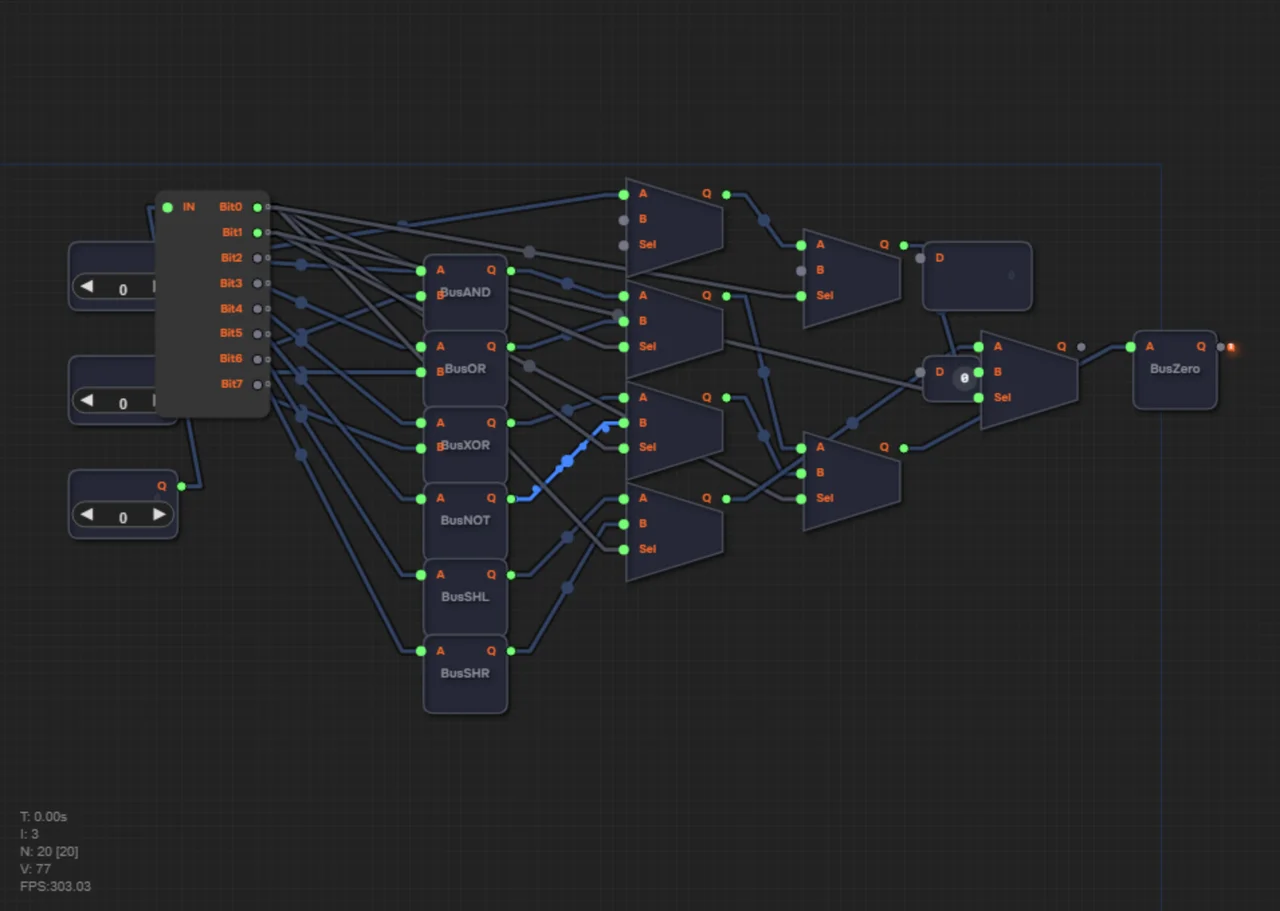
But inside, there is absolutely no magic. In parallel, you simply have an adder and a block of logic gates (AND, OR, XOR). When two numbers enter the ALU, it performs all available operations on them simultaneously!
So how do you get a single correct answer? Very simple. At the output of all these computational blocks sits a large multiplexer. Having received the operation code from the processor (for example, the "Add" instruction), this multiplexer simply selects the right wire with the already-computed sum result, forwards it to the output, and ignores all the other results.
A black box with three stages inside
The ALU takes two 8-bit numbers — A and B — and an operation code (opcode). In return it produces a result, plus a Zero flag that signals whether the result is zero. From the outside it's a "black box"; inside it's a simple three-stage circuit: a decoder (splitting the opcode into bits with a Splitter) → parallel computation blocks → a cascade of multiplexers that selects the final answer.
All operations — at the same time
While you, as a human, decide whether to add or multiply, the circuit doesn't need to choose. Inside the ALU, the adder and all the logic blocks compute their results constantly, always, in parallel. Two numbers arrive — and the adder already outputs A+B, the AND block outputs A&B, the OR block outputs A|B. The processor just picks the one it needs. That's the main trick: speed comes from parallelism, not from quickly switching "modes".
The picking is done by a cascade of multiplexers — we covered them in detail in the article on the multiplexer switch. The control signals come from the decoder, which breaks the opcode into bits. One bit selects between a pair of results, the next between pairs, and so on — a cascade of six multiplexers reduces seven results to one.
The ALU operation table
| Opcode | Operation | Meaning |
|---|---|---|
| 0 | ADD | A + B — addition |
| 1 | AND | A & B — bitwise AND |
| 2 | OR | A | B — bitwise OR |
| 3 | XOR | A ^ B — bitwise exclusive OR |
| 4 | NOT | ~A — bitwise negation of A |
| 5 | SHL | A << 1 — shift left: multiply by 2 |
| 6 | SHR | A >> 1 — shift right: divide by 2 |
Shifts are a little miracle of arithmetic: moving the bits one place left multiplies a number by 2, and one place right divides it by 2. Addition, in turn, relies on the adders described in the article on adder anatomy.
A numeric example: 10 and 6
Let's feed two numbers to the inputs: A = 1010 (that's 10) and B = 0110 (that's 6). Let's see what the ALU outputs for different opcodes.
1. Opcode 0 (ADD): 10 + 6 = 16, in 8 bits — 00010000. (In 4-bit arithmetic, 1010 + 0110 = 1 0000: the one "rolls over" into a carry.)
2. Opcode 1 (AND): 1010 & 0110 = 0010, that is, 2.
3. Opcode 2 (OR): 1010 | 0110 = 1110, that is, 14.
4. Opcode 5 (SHL): A << 1 = 10100 = 20 (in 8 bits — 00010100): the number doubled.
5. Opcode 6 (SHR): A >> 1 = 0101 = 5: the number was divided by 2.
All of this is computed in parallel in a single pass: a pair of numbers goes to the inputs, and the multiplexer simply switches the output to the right wire according to the opcode.
The Zero flag
A separate ALU output is the Zero flag. It equals 1 when the result is zero. This is achieved simply: the result goes to a zero detector (BusZero), which outputs 1 only when all bits on its input are 0. Why is it needed? Through the Zero flag the processor knows that "nothing came out": for example, the conditional jump instruction JZ ("jump if zero") watches exactly this signal.
Common mistakes
- Not connecting all the computation blocks to A and B: every block must receive both operands, or its result is garbage.
- Getting the selector wires tangled: the opcode bits must go to the multiplexers' control inputs, not to their data inputs.
- Forgetting that NOT needs only input A: there's no need to invert B.
Test yourself
Does the ALU perform its operations one by one?
No: inside the ALU all blocks (adder, AND, OR…) compute at the same time, and a multiplexer picks the needed result by the opcode.
How does the ALU know the result is zero?
All eight sum outputs pass through a zero detector: if every bit is 0, the Z flag becomes 1.
How do you turn addition into subtraction?
Invert the bits of the subtrahend and add one — two's complement: A − B = A + (NOT B) + 1.
Summary
1. The ALU is parallel computation blocks plus a multiplexer that picks the required result.
2. Opcodes 0–6 encode the operations: ADD, AND, OR, XOR, NOT, SHL, SHR.
3. A left shift multiplies a number by 2; a right shift divides it by 2.
4. A cascade of six multiplexers reduces seven parallel results to one.
5. The Zero flag shows that the result is zero.
6. The "decoder → operations → MUX" pattern is the standard for ALUs, from simple ones to superscalar designs.
In levels 1.13–1.14 you will first build an operation selector from a cascade of multiplexers, and then assemble a complete 8-bit ALU.