Multiplexer — The Digital Switch
Imagine a railway junction: a passenger train rolls along one set of tracks, a freight train along another, and a single lever in the signal box decides which one continues onto the main line.
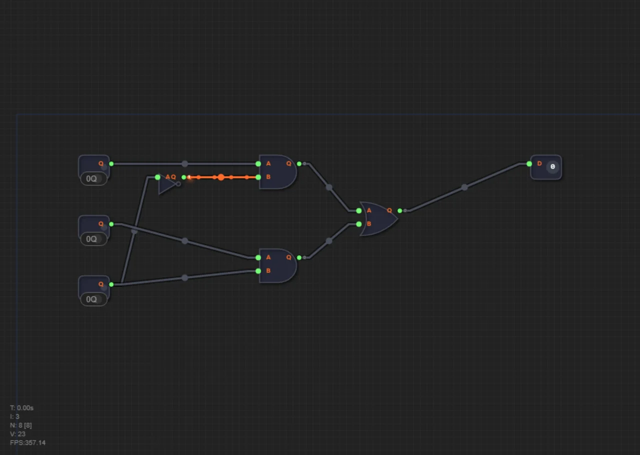
A multiplexer (MUX) is exactly that kind of dispatcher — but electronic. It has two data inputs (A and B) and one special control input called the selector (Sel). When you feed 0 to the selector, the multiplexer passes the data from input A to the output. When you feed 1, it passes the data from input B.
Why does a processor need this? Constantly! For example, to choose where to take the address for a memory read: from the program counter or from an index register. Multiplexers let the processor's hardware change its behavior on the fly, obeying the program code.
Practical example. Inside a processor, a multiplexer constantly picks the address for the next operation. If a jump instruction (JMP) is being executed, the address comes from the instruction operand; otherwise, it arrives from the program counter (PC+1). The multiplexer receives both addresses on inputs A and B, and a signal from the instruction decoder tells it which one to pass through to memory. One chip — hundreds of possible data paths.
Meet the 2-to-1 multiplexer
The simplest multiplexer is 2-to-1: two data inputs, one select input, and one output. It follows a simple rule:
1. Sel = 0 → Q = A.
2. Sel = 1 → Q = B.
Notice: the selector is not data. It's a control wire that makes a decision. That's what fundamentally distinguishes a multiplexer from AND or OR gates, where both inputs are data.
The truth table of a multiplexer
The full behavior of the circuit is described by a truth table of 8 rows — one for each combination of inputs A, B, and Sel:
| A | B | Sel | Q |
|---|---|---|---|
| 0 | 0 | 0 | 0 |
| 0 | 0 | 1 | 0 |
| 0 | 1 | 0 | 0 |
| 0 | 1 | 1 | 1 |
| 1 | 0 | 0 | 1 |
| 1 | 0 | 1 | 0 |
| 1 | 1 | 0 | 1 |
| 1 | 1 | 1 | 1 |
Look at the first and fourth rows: with Sel=0 the output copies A, with Sel=1 it copies B. The selector decides which data make it to the output.
The formula: what a multiplexer is made of
All the magic fits into a single formula:
Q = (A AND NOT Sel) OR (B AND Sel)Let's break it down. When Sel=0:
1. NOT Sel outputs 1 — line A is "open": A AND 1 = A.
2. B AND 0 = 0 — line B is "closed."
3. The OR combines the result: Q = A OR 0 = A.
When Sel=1, it's the opposite: line B opens, line A closes, and B passes to the output. The idea is simple: the selector opens one door and closes the other.
Numeric example: switching the input
Let A = 0 and B = 1. Then:
1. Sel = 0 → Q = A = 0.
2. Sel = 1 → Q = B = 1.
Same multiplexer, same inputs — but the output changes because the selector picked whose data to let through. That's the "electronic switch" in action: the data are the trains, and the selector is the dispatcher moving the lever.
Level 1.9 "Crossroads"
In level 1.9 you will build a multiplexer from basic gates and earn the MUX chip. The circuit follows the formula exactly:
1. Pass Sel through a NOT to get NOT Sel.
2. Feed A and NOT Sel into the first AND.
3. Feed B and Sel into the second AND.
4. Combine both AND outputs with an OR — that's Q.
Check yourself against the truth table: toggle Sel and watch the output switch between A and B. The buses from the previous article work the same way on 8 bits.
Multiplexers inside a processor
There are dozens of multiplexers in a processor, working at different levels. You already know one example — choosing the address source: for an ordinary instruction, the address comes from the program counter (PC), and for a jump, from the instruction operand. One MUX, two address inputs, and the instruction decoder drives the selector.
And it goes further. In level 1.13 "Operation Selection," a cascade of two 8-bit multiplexers (BusMUX) picks the result: ADD, AND, or OR — depending on the OpSelect signal. That's how the processor "decides" which operation to perform, and all the routing is the work of multiplexers. We'll see how this choice turns into real math in the article about the ALU.
Common mistakes
1. Confusing the selector with data. Sel doesn't carry a value — it chooses which input to pass to the output.
2. Forgetting the NOT on the selector. Without the inversion, both lines stay open at once, and the OR "mixes" the inputs.
Summary
1. A 2-to-1 multiplexer has two data inputs (A and B), a selector (Sel), and one output Q.
2. The rule: Sel = 0 → Q = A; Sel = 1 → Q = B.
3. Formula: Q = (A AND NOT Sel) OR (B AND Sel) — the selector opens one line and closes the other.
4. It is built from a NOT, two ANDs, and one OR.
5. Inside a processor, multiplexers pick the address source, the operation result, and much more.
In level 1.9 you will build your first multiplexer — an "electronic switch" at the crossroads of two bit streams — and earn the MUX chip. Then in level 1.13 you'll use a cascade of such multiplexers so the processor itself can choose the operation it needs.