Bus Conflicts and the Address Decoder
In a computer, all devices (RAM, the gamepad, the display) usually sit on one shared highway — the system data bus. Imagine two people trying to speak into the same microphone at once: all you get is garbled noise. In electronics this is called a bus conflict (or bus collision): if two devices drive 1 and 0 onto the bus at the same time, you get a short circuit, or the data turns into garbage.
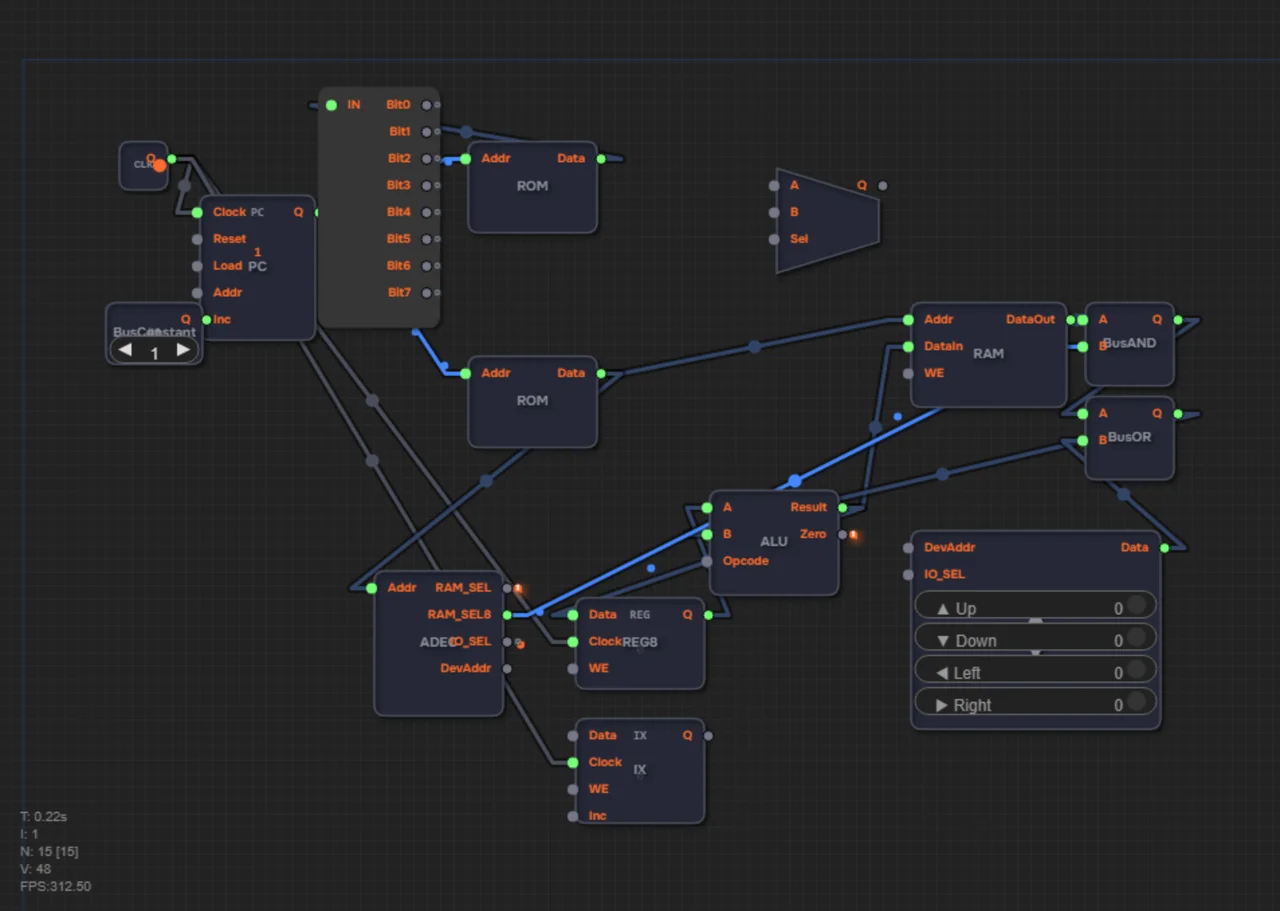
To prevent this, the processor needs a strict traffic controller — the Address Decoder (AddrDecoder). It watches which address the processor is currently accessing and lets exactly one device speak: RAM if the address belongs to it, the gamepad if the address is an I/O port. Everyone else gets the order to stay silent.
In level 2.22 you'll meet this problem in person: RAM and the gamepad share the data bus, and without a decoder they will both push their data at once.
What is an address space
Every device connected to the processor gets its own range of addresses — this is called the address space. In the article about the instruction decoder we looked at how the processor understands an opcode. Now it's time for the other decoder — the address decoder. It doesn't answer "what to do," but "who gets to talk."
In the Ershov Computer the address space is split like this:
| Address range | Device | Select signal |
|---|---|---|
| 0–223 (0x00–0xDF) | RAM — random-access memory | RAM_SEL = 1 |
| 224–255 (0xE0–0xFF) | I/O devices | IO_SEL = 1 |
The I/O range is split further between devices: the gamepad, the random-number generator, and the matrix display get their own ports — we'll cover that in detail in the article about memory-mapped I/O.
The address decoder's outputs
The AddrDecoder produces two signals. RAM_SEL8 is a bus mask: 0xFF when the processor accesses RAM and 0x00 when it accesses an I/O device. IO_SEL is a single bit that says the request went to an I/O port.
Why a mask instead of a simple enable signal? To silence RAM in hardware: the RAM data passes through a BusAND with the RAM_SEL8 mask. If the mask is 0xFF, the data passes through unchanged; if it's 0x00, the output is always zero, and RAM is effectively disconnected from the bus.
The cascade: RAM → BusAND → BusOR
The finished fix looks like this: RAM.DataOut → BusAND.A, AddrDecoder.RAM_SEL8 → BusAND.B, BusAND output → BusOR, and the BusOR result goes onto the data bus and then into ALU8.B. The gamepad connects to the second input of the BusOR.
When the address belongs to RAM, the mask lets RAM data through and the gamepad simply isn't active. When the address belongs to an I/O device, the mask zeroes out the RAM data and only the gamepad remains on the bus. A conflict becomes physically impossible.
Two addresses, in numbers
Let's trace two cases. Address 200: it lies in the 0–223 range, so it's RAM. The decoder sets RAM_SEL8 = 0xFF, RAM data passes through the BusAND unchanged, and the gamepad is masked out. The ALU sees the contents of cell 200.
Now address 254: it falls into the 224–255 range, which is the gamepad port. RAM_SEL8 = 0x00 — every bit of RAM data is zeroed, RAM is silent. Only the gamepad button state remains on the bus. One device, one source, no garbage.
Step by step: 1) ROM puts the address on AddrDecoder.Addr; 2) the decoder compares it with the ranges; 3) it sets RAM_SEL8 and IO_SEL; 4) the BusAND/BusOR cascade leaves exactly one talker on the bus.
Common mistakes
1. Forgetting to connect AddrDecoder.Addr to the ROM: the decoder doesn't know which address is being accessed and produces wrong select signals.
2. Connecting RAM straight to the bus without a BusAND: RAM will drive data even when an I/O port is being accessed.
3. Thinking "two sources on the bus is fine": that's a short circuit at the logic level, not a race where someone wins.
Summary
1. The data bus is shared, so only one device may drive it at a time.
2. The address space is split: 0–223 is RAM, 224–255 is I/O devices.
3. The AddrDecoder outputs a RAM_SEL8 mask (0xFF or 0x00) and the IO_SEL bit.
4. The cascade RAM → BusAND (with the mask) → BusOR (with the gamepad) makes conflicts impossible in hardware.
5. Address 200 reads RAM, address 254 reads the gamepad — never at the same time.
In level 2.22 you will wire up the Address Decoder and build the BusAND/BusOR cascade so that RAM and the gamepad never drive the bus simultaneously. After that the computer learns to read buttons — and we move on to input/output.